Chapter 5. Getting Started
5.1 Unpacking
Güralp Radian Post-hole systems are most commonly delivered inside rugged Peli™-cases with wheels, measuring 96 x 40 x 15 cm. This packaging is specifically designed for the Radian Post-hole system and should be re-used whenever you need to transport the instrument.
Warning: The Radian Radian Post-hole system weighs in excess of 12 kg. Improper storage or handling may cause injury, disability or death. Always follow recognised safety procedures for heavy equipment handling.
Caution: The Radian Post-hole system contains sensitive mechanical components which can be damaged by mishandling. If you are at all unsure about the handling or installation of the device, you should contact Güralp Systems for assistance.
Do not bump or jolt any part of the equipment when handling or unpacking.
Do not kink or walk on any cables (especially on rough surfaces such as gravel), nor allow the cables to become trapped under the heavy items.
Do not connect the instrument to power sources except where instructed.
Never ground any of the output signal lines from the sensor.
Take care with the connector pins and plugs. Pins can be delicate and may bend/break easily.
5.2 System set-up
Güralp highly recommends testing and gaining familiarity with the Radian system at your lab before installation in an outdoors environment.
A typical set-up for the Radian system (including an optional analogue sensor) is shown in the figure below.
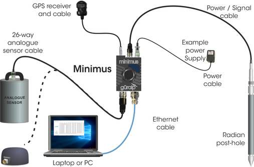
To get started, connect the cables as shown and as described in Section 4.1.4, Section 4.4.1, Section 4.5.1 and Section 4.1 of MAN-MIN-0001.
Connect the Minimus/Surface Interface Unit (SIU) to a 10-36 V DC power supply which will, in turn, provide power to the Radian.
5.3 Software installation and set-up
To view live waveforms and to control and configure the Radian, SIU and other connected sensors, you will need to use Güralp Discovery software. Using a web browser, visit
https://www.guralp.com/sw/download-discovery.shtml
and download the appropriate file for your PC. Run the file and follow the instructions on screen.
Full details of installation and upgrading are in Appendix 4 of MAN-MIN-0001.
When you open Discovery, it displays a main window which shows both locally and remotely connected instruments. If you close this main window, Discovery will quit.
Discovery will initially “listen” for connected instruments on your local network. This mode can be refreshed by selecting the “Scan Locally” button or by keying  +
+ .
.
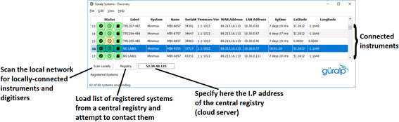
Instruments are referred to in Discovery as follows:
Minimus: an analogue sensor directly attached to the SIU and the SIU's internal sensors are all referred to as Instrument 0, whereas Instruments connected through the digital port (i.e. Radian) are defined as Instruments 1, 2, 3… etc.
Minimus+: the first analogue sensor directly attached to the SIU and the SIU's internal sensors are all referred to as Instrument 0. The second analogue sensor directly attached to the SIU is referred to as Instrument 1. Digital instruments connected through the digital port (i.e. Radian) are defined as Instruments 2, 3, 4… etc.
5.4 Viewing waveforms and system state-of-health
Please refer to Section 4.3 of MAN-MIN-0001 for full details on viewing waveforms and state-of-health information from the Radian.
5.4.1 Using Güralp GüVü app on Android and iOS devices
Please refer to Section 6 of MAN-MIN-0001 for full usage details on Güralp GüVü.
5.5 Radian bore-hole: control of hole-locks
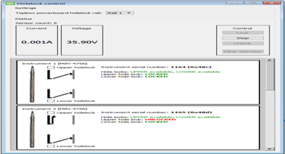
Hole-locks on connected Radian bore-hole instruments can be easily controlled using Güralp Discovery. To access the hole-lock control tools, launch the Control Centre by right-clicking on an active entry in Discovery's main window.
Click on the “Hole-lock control” button  to open the corresponding window: this shows the status of the upper and lower hole-locks of all the Radians connected to the selected SIU.
The Settings section allows selection of the output power-rail used to provide power to the hole-lock. This is always "Rail 1" in standard units so this setting must be left unchanged unless the SIU has a customised configuration.
Under "Status", two boxes show the current being drawn and the voltage supplied to the hole-lock motors. These values are updated in real time.
There is also a section labelled "Control", which is active when one of the check-boxes for the hole-locks in the graphical section at the bottom of the page is selected.
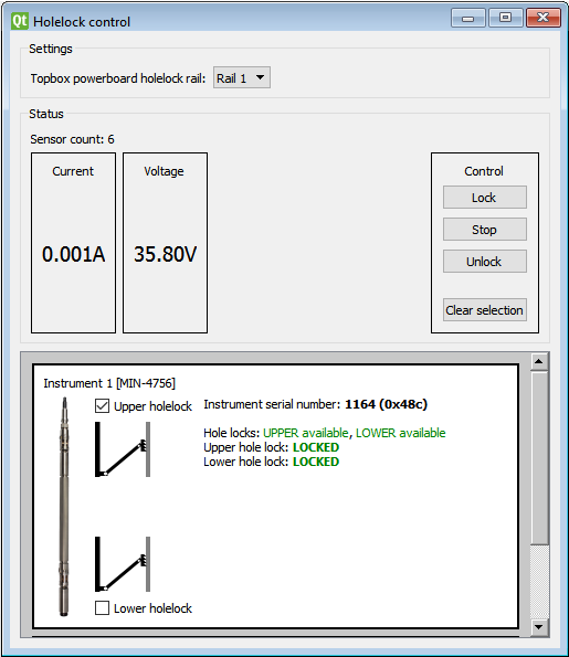
Within the graphical section:
if the hole-lock is locked, the status will be displayed as LOCKED;
if the hole-lock is unlocked, the status will be displayed as UNLOCKED.
To retract a hole-lock, tick the relevant check-box for the hole-lock and then click the  button; to deploy a hole-lock, click the
  button.
During the locking/unlocking process, the status LOCKING and UNLOCKING will be shown, respectively. You can stop the locking or unlocking process by pressing the  button or by selecting a different hole-lock.
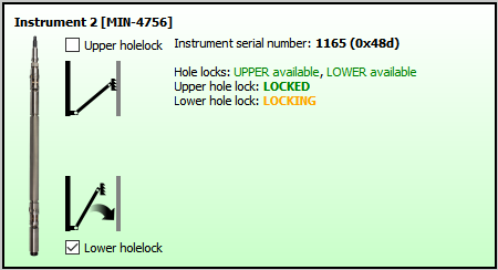
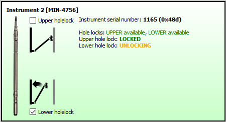
If the hole-lock is stopped while it is not completely locked or unlocked, the status MIDLOCK will be displayed.
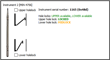
When the locking or unlocking action terminates and the hole-lock has reached the desired status, locked or unlocked, a sound is generated.
5.5.1 Locking sequence
Locking should always proceed from the bottom upwards, so:
For a single Radian, the lower hole-lock should be deployed before the upper hole-lock.
Note: If this order is not respected, a warning message is displayed. It is possible to proceed anyway, by-passing this warning, by clicking on the “Yes” button.
If more than one Radian bore-hole if connected in a string, proceed as follows:
Lock the lower hole-lock of the deepest instrument
Lock the upper hole-lock of the deepest instrument
Lock the lower hole-lock of the next-deepest instrument
Lock the upper hole-lock of the next-deepest instrument
Repeat steps 3 and 4 until the uppermost instrument is locked.
Note: If this order is not respected, a warning message is displayed. It is possible to proceed anyway, by-passing this warning, by clicking on the “Yes” button.
5.5.2 Unlocking sequence
Caution: Always provide secure support by tensioning the load-bearing cable before unlocking a deployed instrument. Failure to do so can result in the instrument dropping in an uncontrolled manner, risking damage to the instrument and/or cable.
When unlocking strings of instruments, take up the slack and re-tension the load-bearing cable after unlocking each individual instrument. The required tension will rise after each instrument is unlocked.
Unlocking should always proceed from the top downwards, so:
For a single radian, the upper hole-lock should be retracted before the upper hole-lock.
Note: If this order is not respected, a warning message is displayed. It is possible to proceed anyway, by-passing this warning, by clicking on the “Yes” button.
If more than one Radian bore-hole if connected in a string, proceed as follows:
Retract the upper hole-lock of the shallowest instrument
Retract the lower hole-lock of the shallowest instrument
Retract the upper hole-lock of the next-shallowest instrument
Retract the lower hole-lock of the next-shallowest instrument
Repeat steps 3 and 4 until the deepest instrument is unlocked.
Note: If this order is not respected, a warning message is displayed. It is possible to proceed anyway, by-passing this warning, by clicking on the “Yes” button.
Caution: If this order is not respected, a warning message is displayed. It is possible to proceed anyway, by-passing this warning, by clicking on the “Yes” button. Do not do this on a deployed system unless advised to do so by Güralp staff.