Chapter 7. Configuration and control of Radian instruments
7.1 Mass centring
By default, the Radian automatically keeps its masses centred. The Radian’s unique motorised mass centring system allows the masses to centre when the instrument is installed at any angle.
To perform a manual centring of the masses, launch the Minimus or Minimus+ Control Centre by right-clicking on the device in the Discovery main window.
The Radian is identified with the title “Instrument 1” when connected to a Minimus.
The Radian is defined with the title “Instrument 2” when connected to a Minimus+.
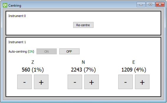
The mass position values in counts of the three components are showed in real-time under the corresponding component indicators (Z, N, E).
The mass positions can be adjusted manually:
click the
 button to decrease the mass position value (i.e. make it less positive or more negative).
click the
 button to increase the mass position value (i.e. make it more positive or less negative).
In action starts the auto-centring procedure. The first stage consists in a rough mechanical centring which it is followed by a more accurate electrical centring sequence that lasts 7 minutes.
When the auto-centring is enabled, the centring procedure is activated as soon as the percentage reaches ±100%. To turn off Automatic Mass Centring, select the  button in the Auto Centring option (not recommended). To restore the default setting, click on the
  button.
7.2 Calibration
7.2.1 Seismic channels calibration
Calibration is a procedure used to verify or measure the frequency response and sensitivity of a sensor. It relates the output voltage to the actual corresponding ground motion.
The Radian is a digital sensor and it calibrated once in the factory. The calibration parameters are saved in the instrument and automatically transmitted to the Minimus digitiser during each boot-up phase.
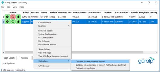
To access the Radian’s calibration page, go to Discovery’s main screen, right-click on the instrument and select “Calibration” → “Calibration Page Editor”.
Please refer to Section 5.11.4 of MAN-MIN-0001 for full details on using the Calibration Page Editor.
7.2.2 Accelerometer calibration
Caution: The calibration of the Radian MEMS accelerometer is carried-out in the factory. Please, follow the procedure below only in case suggested by Güralp. It is recommended to use the standing jigs provided on request.
The Radian is supplied with an internal three-axis MEMS accelerometer with a measuring range of ±2 g. The accelerometer helps to determine the Radian’s position in space (pitch and roll).
The MEMS accelerometer should be calibrated once in the factory and it is not required to repeat the calibration on the deployment site because the Earth’s gravitational pull can be considered constant in each part of the world.
To calibrate the Radian’s accelerometer, go to Discovery’s main screen, right-click on the instrument and select “Calibration” → “Calibrate Accelerometer of Sensor1”.
In the calibration window (see below), the left-hand panel gives a three-dimensional visualisation of the Radian’s orientation (left) with respect to a fixed reference frame (right). The view can be rotated by sliding the “Viewport” bar. The labels, “F”, “B”, “L” and “R” refer to the Front (North), Back (South), Left (West) and Right (East) directions of the Radian respectively.
The right-hand side of the panel gives real-time values of accelerometer measurements, with calculated angles of pitch and roll.
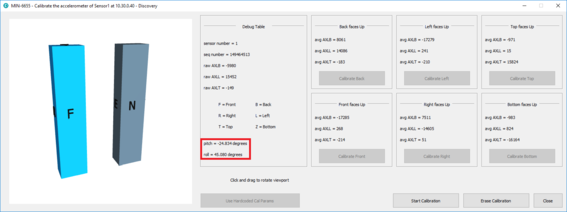
The calibration of the accelerometer is performed in six stages, one for each combination of polarity and axis of the instrument.
The North face of the Radian can be determined from where the label is attached or from the connector (the larger orientation groove points North/Front).
The Top face of the Radian is the one where the cable is connected and the Bottom face is the one with the pilot cone.
Note: It is recommended to use an external digital level or inclinometer to make sure that the Radian is perfectly aligned to the direction of interested. The jigs are required to obtain an accurate result and they are available on request.
To perform the calibration follow the steps below:
Using the jigs and the inclinometer, accurately position the Radian on a horizontal surface with the Back facing up, click on "Start Calibration" button and wait for 15-20 seconds without moving the Radian;
Click on the “Calibrate Back” button;
Rotate the Radian and, using the jigs and inclinometer, accurately position the it with the Left facing up, wait for 15-20 seconds without moving the Radian;
Click on the “Calibrate Left” button;
Rotate the Radian and, using the jigs and inclinometer, accurately position the it with the Front facing up, wait for 15-20 seconds without moving the Radian;
Click on the “Calibrate Front” button;
Rotate the Radian and, using the jigs and inclinometer, accurately position the it with the Right facing up, wait for 15-20 seconds without moving the Radian;
Click on the “Calibrate Right” button;
Using the jigs and inclinometer, accurately position the Radian against a vertical surface with the Top facing up, wait for 15-20 seconds without moving the Radian;
Click on the “Calibrate Top” button;
Rotate the Radian upside-down and, using the jigs and inclinometer, accurately position the it against a vertical surface with the Bottom facing up, wait for 15-20 seconds without moving the Radian;
Click on the “Calibrate Bottom” button;
Click on “Close” button.
7.2.3 Magnetometer calibration
The Radian contains an internal three-axis magnetometer that can measure the Earth’s magnetic field (in nanoTeslas) allowing the instrument to be used as a digital compass. The magnetometer can be affected by magnetic and environmental interference (including other electronic equipment), so it must be carried out at least several metres away from any electronic devices, any magnetic objects or any large metallic objects.
The magnetometer uses information from the internal MEMS accelerometer (pitch and roll) to determine the Radian’s position in space. The magnetometer helps to determine the Radian’s horizontal orientation (yaw). In addition, the magnetometer may be used to determine relative changes in the near-field magnetic field that may be caused by noise sources.
The magnetometer should be calibrated to find the direction of maximum magnetic field strength, which may be interpreted as Magnetic North. If the magnetometer is being used for this purpose, magnetic declination (http://www.ngdc.noaa.gov/geomag-web/#declination) must be accounted for to estimated the orientation of True North.
The magnetometer should be re-calibrated upon delivery of the Radian and, ideally, every time the instrument is moved to a different location, in order to account for local magnetic field variations.
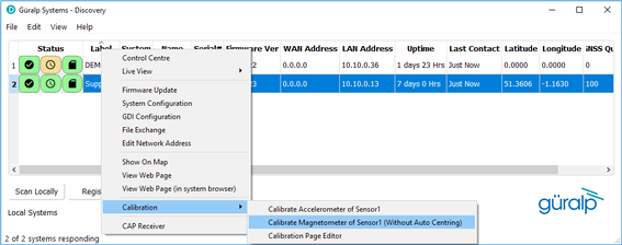
To proceed, right-click on the instrument in Discovery and select “Calibration” → “Calibrate Magnetometer of Sensor1 (Without Auto Centring)”.
In the calibration window, the left-hand panel gives a three-dimensional visualisation of the Radian’s orientation (as described previously when discussing the accelerometer calibration window).
When the calibration process is started, the right-hand side of the panel gives real-time values of accelerometer and magnetometer measurements, with calculated angles of yaw, pitch and roll.
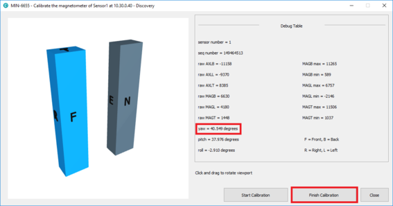
To perform the calibration, follow the steps below:
Click on “Start Calibration” button;
Rotate the Radian in all the possible angles. This is so that all of the faces are exposed to the maximum magnetic field present on the site.
Keep moving the Radian around until the max and min values shown on the right-side column stop being updated.
Click on “Finish Calibration” button when the max and min values are stable.
Click on “Close” button.