Chapter 6. Recommended Field Procedures
Note: The Radian connector is fitted with two O-rings to guarantee the waterproofing. To connect the cable, maintain the Radian in vertical position and roughly align the grooves in the plug with the tongues in the socket before inserting the cable connector. Kindly push and rotate the connector until it lines up perfectly. Push it to down until it reaches the end stop. Screw the fixing ring down to the end of the thread.
Caution: The air compressed inside the connector can push in the opposite direction because of the O-rings. Do not use the fixing ring to help you pushing the connector inside the Radian to prevent any damage on the thread.
6.1 Post-hole installation
Compared to traditional vault-style installations, the post-hole method has the potential to save significant time and resources (material, labour), without loss of performance. The technique minimises thermal effects and improves noise performance, especially for horizontal sensor components at low frequencies.
To minimise surface noise effects, you should ensure that the hole is at least one metre deeper than the full length of the Radian Post-hole.
6.1.1 Procedure
Prior to arrive at the final installation site, you will need to calibrate the Radian’s internal magnetometer.
Prior to arriving at the installation site, ensure that a microSD card (if appropriate, correctly formatted and with enough free space) is inserted into the SIU’s card slot.
The magnetometer should be calibrated in a region where the local declination is known by pointing the axis towards maximum field components.
Create a hole for the installation using a portable motorised- or hand-auger. Ideally, the hole should be at least two metres deep and 65 cm wide.
Note: Note that, due to the Radian’s unique sensors (±180° tilt tolerance), the hole does not need to be exactly vertical.
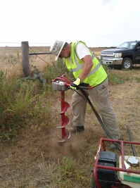
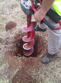
Post-hole installation using a motorised hand auger
Clean the post-hole, ensuring that there is no loose material around the mouth of the hole or on its base.
Ensure that the bayonet connector joining the Radian to its power/signal cable is firmly tightened and free of dirt.
Add a 15 cm thick layer of packing material to the bottom of the hole. A mixture of 3 mm grade angular coarse grit with around 30% medium grit gives good results, allowing any water to permeate and soak away, whilst leaving the packing material moist. Slightly moisten the packing material in the hole and ram it firmly down, if possible.
Gently lower the vertically-hanging instrument to the bottom of the post-hole using the strain-relief power/signal cable. Keep the cable taut.
Note: Note that, due to the Radian’s unique sensors (±180° tilt tolerance), the instrument does not need to be exactly vertical within the hole and it does not need to be aligned with north.
Continue filling with the packing material and moistening, while keeping the power/signal cable taut until the instrument is fully buried.
Slacken the power/signal cable.
Install the SIU (and, if applicable, a power source such as a lead-acid battery) in a separate waterproof enclosure (e.g. a Peli™-case).
Attach the free end of the power/signal cable to the “DIGITAL” port on the SIU. Connect the rest of the cables and peripherals to the SIU (as shown/described in Section 5.2).
Power up the SIU and connect to it using either Discovery, Scream! or GüVü.
Carry out a stomp test to ensure that the waveforms look acceptable.
If necessary, configure the Sensor, Networking and Recording settings (see Section 7).
Back-fill the remainder of the hole with the originally excavated soil/material.
6.2 Single-instrument bore-hole installation
6.2.1 Installation using hole-locks
For a bore-hole installation, you should have been provided with a winch and tripod from Güralp.
The key benefit of the Radian instrument is that it can operate at any angle so excellent seismic data can be obtained even if the the bore-hole is not completely vertical.
Before installing any instrument in a bore-hole, you should prepare the installation site.
Clean the area around the bore-hole head, so there is clear access all around it.
Keep the bore-hole capped at all times except when inserting or removing the instrument, so that debris and tools do not accidentally fall in.
Lay out the cables beside the bore-hole, or set up a cable drum nearby, so that they do not become tangled.
Ensure the tripod is tall enough to hang the entire sonde from it, with the sensor clear of the ground.
Use a winch with a depth gauge, if possible, or measure out the cable beforehand.
Test the hole-lock mechanism before installing the sensor (see Section 5.5).
6.2.1.1 Procedure
Connect the power/signal cable to the connector on top of the sensor. Fully tighten the knurled nut to its end stop using firm hand pressure.
Using the winch, hoist up the sensor package until it is hanging by the power/signal cable.
Position the instrument over the top of the bore-hole. Do not allow it to drag across the ground.
Lower the instrument so that its base is just level with the bore-hole mouth. If there is a depth gauge on the winch, set it to zero now.
Continue to lower the instrument to a depth of about one metre, so that the instrument is still visible.
Power up the Surface Interface Unit and Instrument, and extend the hole-lock arm (see Section 5.5) to check that it fits your bore-hole. Monitor the hole-lock current: it should dip slightly as the arm touches the casing, then drop to zero when it is fully extended. Check that the instrument is firmly anchored to the bore-hole casing by attempting to slacken the load bearing cable. If it remains taut, the instrument is still loose within the bore-hole. Do not proceed with installation in this case. Instead, you should either move the instrument to a narrower section of the bore-hole and try again, or contact Güralp Systems to fit a wider hole-lock, quoting accurate measurements of your bore-hole.
Check that the sensor is functioning correctly by looking at the waveforms being shown on, e.g., Discovery software. If the sensor fails to register ground movements, contact Güralp Systems.
Re-tension the load-bearing cable and retract the hole-lock jaws using Discovery software.
Gently lower the sensor to the required depth. Fix the sensor system into the bore-hole using the hole-lock arm.
Lower the cable by around 30 cm to provide some slack in the cable.
Clamp the cable to the top of the bore-hole.
The winch can now be dismantled and removed from site.
6.2.2 Installation using sand back-fill
Dry sand back-fill is a convenient and effective way of installing a single Radian bore-hole instrument in a time-stable environment. The presence of sand not only fixes the sensor in place at the bottom of the hole, but also reduces noise due to air convection.
The ideal type of sand to use is the fine, kiln-dried sand supplied for use in children's play sandpits. This is readily available in airtight bags, is thoroughly washed and clean, and will contain little sediment (when dried out after wetting, sand containing foreign matter may solidify and form a concrete-like substance, permanently trapping the sensor in position.) This sand is suitable for use in both dry and damp bore-holes.
In the procedure outlined below, the sensor will rest on a pad of sand around 300 mm thick. This pad will absorb any residual moisture at the bottom of the bore-hole, and ensure that the surroundings of the instrument are kept dry.
After positioning the sensor, more sand is added to fill the space between it and the bore-hole casing, holding it firmly in place. The sand should reach within 30 mm of the top of the instrument, but should not cover it. This way, the instrument can be more easily recovered when it requires maintenance or replacement. This is particularly important if the bore-hole is not completely dry, since moist sand does not flow well.
6.2.2.1 Procedure
Measure or calculate the physical volume of the unit which is to be installed in the bore-hole (the volume of a cylinder is given by v = πr2h where r is the radius and h is the height). Also measure the internal diameter of the bore-hole.
Measure and pour in a sufficient quantity of sand to fill the bore-hole to a depth of around 300 mm.
Connect the power/signal cable to the connector on top of the sensor. Fully tighten the bayonet connector nut to its end stop.
Using a winch, hoist up the sensor package until it is hanging by the power/signal cable.
Position the instrument over the top of the bore-hole. Do not allow it to drag across the ground.
Lower the instrument so that its base is just level with the bore-hole mouth. If there is a depth gauge on the winch, set it to zero now.
Begin lowering the sensor down the bore-hole, keeping track of the depth reached.
Whilst monitoring the depth of the sensor, carefully approach the sand layer at the bottom of the bore-hole. The tension of the power/signal cable will reduce when the sensor makes contact with the sand.
Note: If the tension of the power/signal cable reduces before the sensor has reached the sand layer, the sonde may have become caught on a bad joint or lip in the bore-hole; carefully raise and lower the instrument to free it.
When the sonde reaches the bottom, use the winch to lift the package slightly, re-tensioning the cable. This ensures that the sensor is hanging vertically within the bore-hole and is no longer in contact with the sand bed.
Calculate the volume of dry sand required to fill the gap between the sensor and the bore-hole liner to the level of the top of the sensor (v = πr²h using the internal radius of the bore-hole, from which you should subtract the volume of the instrument, as determined in step 1).
Pour this sand into the bore-hole. If you can, check how much of the sensor is covered with sand. Güralp can provide bore-hole cameras with built-in illumination for this purpose. Do not over-fill the hole.
Carefully slacken the power/signal cable to secure the installation within the bore-hole.
Without pulling or lifting the sensor, lightly shake the cables to remove any sand that may have fallen onto them.
6.3 Multi-instrument bore-hole installation (i.e. VSP tool)
The maximum number of instruments that can be strung together is six; this is due to limitations in the voltage that can be carried through to the vertical array and the safe loading strength of the power/signal cables.
6.3.1 Procedure
Caution: To prevent ingress of moisture, make sure that an end cap is securely fitted to the bottom of the lowermost instrument
Connect a 15 metre, 5 mm diameter slave cable to the power/signal cable above the lowermost sensor
Winch this assembly into the bore-hole until the top of the cable is almost level with the top of the bore-hole
Slide the cable trap plate over the cable and rest it on the top of the bore-hole
Continue to winch the assembly down until the weight is taken entirely by the cable trap plate.
Remove the lifting eye cable termination from the cable and attach the bottom of the next sensor to the exposed cable
Connect a the 15 metre, 5 mm diameter slave cable to the power/signal cable above this sensor
Lift the deployed assembly slightly to allow the cable trap plate to be removed
Repeat from step 3.