Chapter 3. Installation
3.1 Unpacking and packing
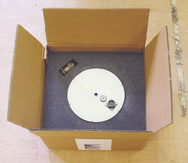
The CMG-5T accelerometer is delivered in a single cardboard box with foam rubber lining. The packaging is specifically designed for the 5T and should be reused whenever you need to transport the sensor. Please note any damage to the packaging when you receive the equipment, and unpack on a clean surface. The package should contain:
the accelerometer;
a signal connection cable (if ordered); and
a connector, of type 06F-14-19S.
Place the accelerometer on a clean surface, and identify:
The signal cable connector on the top of the unit;
The N/S orientation line, engraved on the lid;
The N/S orientation pointers (studs);
The bubble level;
The screw-on cover for the output offset adjuster (see below);
The central hole for the main fixing bolt; and
The serial number. If you need to request the sensor production history, you will need to quote either the serial number of the sensor or the works order number, which is also provided on the calibration sheet.
3.2 Initial testing
To test the 5T before installation, you will need a power source which can deliver 100 mA at 10 to 36 V and a digital voltmeter (DVM) with 1 and 10 V ranges. Also ensure that the supplied cable is connected with the correct polarity (see the Appendices).
To make it easier to measure the output from the sensor, you can use a hand-held Control Unit or a custom interface box, which can be manufactured from a screw clamp connector block. This will simplify the connections to the appropriate connector pin outputs.
Place the 5T sensor on a flat, horizontal surface.
Connect the power supply, observing the correct polarity for the cable supplied, and switch on.
Connect the voltmeter to pins L and M of the output connector (corresponding to the low gain vertical component.) Measure the output of the low gain vertical component. The steady output voltage should be about zero (± 10 mV).
Repeat the measurement for the N/S and E/W low-gain component outputs (pins C/D and K/U respectively).
Now gently turn the sensor onto its side, propping it carefully to prevent rolling.
The low gain vertical component should now read about –5 V, corresponding to –1g.
Roll the instrument until the N/S line is vertical, with N at the top.
The low gain N/S component should now read +5 V, corresponding to +1g.
Roll the instrument until the N/S line is horizontal.
The low gain E/W component should now read +5 V.
If the performance so far has been as expected, the instrument may be assumed to be in working order and you may proceed to install the unit for trial recording tests. Most likely, however, you will need to adjust the mass deflection offset (see Section 3.4, page 10.)
3.3 Installing the sensor
You will need a solid surface such as a concrete floor to install the 5T.
If you are in any doubt about how to install the sensor, you should contact Güralp Systems.
Prepare the surface by scribing a N/S orientation line, and installing a grouted-in fixing bolt around the middle of the line. A 6 mm (0.25 in) threaded stud is suitable, or an expanding-nut rock bolt or anchor terminating in a threaded stud. The bolt should be about 120 mm (5 in) long.
Place the accelerometer over the stud, on the scribed base-line, and rotate to bring the orientation line and studs accurately in alignment with it. The accelerometer has no levelling feet, but can use an internal simulated level adjustment to compensate as long as it is fixed to a hard, clean surface within 1 ° of the horizontal.
Fix the accelerometer in place using a fixing nut with spring washer. Do not over-tighten.
If required, make a screening box for the sensor, to shield it from draughts and sharp changes of temperature. A suitable box can be constructed from expanded polystyrene slabs (e.g. 5 cm building insulation slabs) with sealed joints between them and a hole drilled for the connector. You can then use high-grade glass fibre sealing tape to fix the leads in position and fasten the box to the mounting surface. Commercial duct sealing tape is ideal.
Connect the sensor to your digitizing equipment or Control Unit to start receiving signals.
3.3.1 Temporary installations
5T sensors are ideal for monitoring vibrations at field sites, owing to their ruggedness, high sensitivity and ease of deployment. Temporary installations will usually be in hand-dug pits or machine-augered holes. Once a level base is made in the floor, the accelerometer can be sited there and covered with a box or bucket. One way to produce a level base is to use a hard-setting liquid:
Prepare a quick-setting cement/sand mixture, and pour it into the hole.
“Puddle” the cement by vibrating it until it is fully liquefied, allowing its surface to level out.
Depending on the temperature and type of cement used, the mixture will set over the next 2 to 12 hours.
Install the sensor as above, cover, and back-fill the emplacement with soil, sand, or polystyrene beads.
Cover the hole with a turf-capped board to exclude wind noise and provide a stable thermal environment.
If you prefer, you can use quicker-setting plaster or polyester mixtures to provide a mounting surface. However, you must take care to prevent the liquid leaking away by “proofing” the hole beforehand. Dental plaster, or similar mixtures, may need reinforcing with sacking or muslin.
3.3.2 Installation in Hazardous environments
The fully enclosed aluminium case design of the 5T instrument makes it suitable for use in hazardous environments where electrical discharges due to the build up of static charge could lead to the ignition of flammable gasses. To ensure safe operation in these conditions, the metal case of the instrument must be electrically bonded ('earthed') to the structure on which it is mounted, forming a path to safely discharge static charge.
Where electrical bonding ('earthing') is required during the installation of a 5T instrument, the central mounting hole that extends through the instrument should be used as the connection point. This is electrically connected to all other parts of the sensor case. Connection can be made by either a cable from a local earthing point terminated in a 8mm ring tag or via the mounting bolt itself.
3.4 Centring the 5T
Once it is installed, you should centre the instrument ready for use. The offset can be as much as the entire output range of the accelerometer, which corresponds to around 1 ° from the horizontal or vertical. You can check that the 5T is within this range by using the bubble level on the top of the casing: as long as the bubble lies completely within the scribed ring, the remaining adjustments can be made internally.
Remove the screwed cover protecting the level adjusters. The cavity contains three adjustment screws, which are arranged as shown in the diagram below:
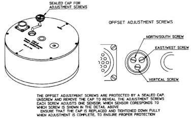
Power up the sensor, and connect a digital multimeter to its low-gain vertical outputs (pins L and M). Alternatively, use a Güralp Systems CMG-5T hand-held control unit to monitor the outputs more easily.
Adjust the vertical screw until the output voltage reads zero.
Repeat steps 2 and 3 for the N/S and E/W channels, (pins C/D and K/U respectively).
If necessary, continue to adjust each channel in turn until consistent results are obtained on all three channels.
Repeat steps 2 to 5 using the high-gain outputs, if available, and refine the settings as far as possible.
Replace the protective cover firmly, to keep the instrument's electronics protected from water and dust.
After the cover is installed, the accelerometer outputs may drift until the system establishes temperature equilibrium with its environment and the sensor settles down in its position. If required, the offset adjustment can be repeated to achieve a better output offset. With experience, it should be possible to reduce the output level to less than ± 1 mV.
3.5 Electrical connections
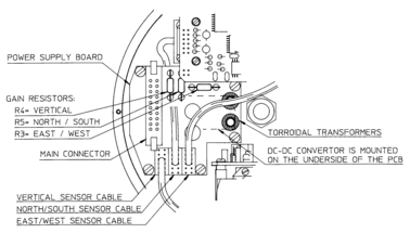
Each channel inside the 5T sensor has four output lines: a pair of differential outputs with low gain and another pair with high (around × 10) gain.
Optionally, the second gain block can be configured at the factory to act as a high-pass filter to remove the DC offset at the output terminal. If this is the case, the gain at these outputs will be set to × 1 (unity), with a separate circuit board providing a filter with a corner frequency of 0.05 Hz (20 s) or 0.025 Hz (40 s). The output offsets of a high-pass output cannot be zeroed using the DC offset adjustment screws; in any case, this offset should not be more than ± 1 mV. The high-pass output is likely to take around five times the time constant of the high-pass circuit to settle down. This time constant is provided on the calibration sheet, together with accurately-measured frequency values.
The two pairs of output lines are balanced about signal ground so that either differential drive or single-ended drives of opposite polarity (phase) are available. For a single-ended drive, the signal ground must be used as the signal return path. You must not ground any of the active output lines, as this would allow damaging currents to flow through the output circuits. Also, if single-ended outputs are used, the positive acceleration outputs must be interfaced to the recorder.
For distances up to 10 metres, you can connect the sensor outputs using balanced, screened twin lines terminated with a high-impedance differential input amplifier. The sensor outputs have a nominal impedance of 47 Ω.
The 5T is normally powered directly from a connected Güralp digitizer through the 10-way connector, although you can use a separate 10 – 36 V DC power supply if you wish. The current consumption from a 12 V supply is about 53 mA. An isolated DC–DC converter installed inside the sensor housing forms the main part of the 5T unit's power supply; its filtered outputs provide the ±12 V required to operate the sensor electronics. The DC–DC converter is protected against polarity reversal.
The calibration signal and calibration enable inputs are referenced to the signal ground. If you are using a Güralp digitizer, these lines can be connected directly to its calibration lines. Otherwise, you will need to provide a 5 V logic level on the calibration enable input in order to calibrate the instrument. The signal ground line is used as the return for both calibration enable and calibration signal lines. See Chapter 4 for more details.
3.5.1 Modifying the sensitivity
This section applies to instruments before serial number T5225 only.
The primary gain block of the 5T is normally set at × 1 (unity). If higher sensitivity is required, the gain of the instrument can be altered by inserting gain-setting resistors onto the power supply board of the unit:
If G is the gain change you require, then the value of the resistors to insert is given by the formula
R = 10000 / (G – 1)
Care must be taken when soldering these resistors to the circuit board, as overheating the terminal could easily damage surrounding circuit elements.