Chapter 5. Inside the 5T
The 5T unit is constructed of hard-anodised aluminium with “O” rings throughout, ensuring a completely waterproof housing.
Inside, the mass of the vertical and horizontal components is attached to the rigid frame with parallel leaf springs. The geometry of the spring spacing, together with the symmetrical design, ensures large cross-axis rejection. The sensor mass is centred between two capacitor plates, and moves in a true straight line, with no swinging motion. Feedback coils are attached either side of the sensor mass, forming a constant-flux force feedback transducer.
The vertical and horizontal sensors are identical in mechanical construction; the vertical sensor's mass spring system is adjusted to compensate for gravity. They are mounted directly onto the base, with the sensor electronics fixed onto the rigid sensor frame. A single-row, 12-way surface mount R/A Molex connector joins each sensor to the main power supply circuit board.
The signal and feedback circuits inside the 5T accelerometer are arranged according to the following diagram:
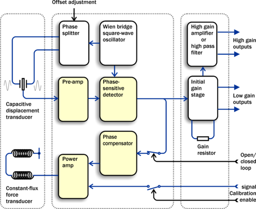
The mass and the capacitor plates are energised by a two-phase transformer driver, forming a differential capacitor. This acts as a capacitive transducer, whose signal is then demodulated with a phase-sensitive detector. The accelerometer feedback loop is completed with a feedback loop compensator and a feedback force transducer power amp.
The differential output amplifier scales the output sensor sensitivity and a second stage amplifier can be configured (at the factory) either as a further cascaded gain stage or as a high-pass filter with unity gain.
5.1 The force transducer
The CMG-5T is a force feedback strong-motion accelerometer which uses a coil and magnet system to generate the restoring feedback force. Such accelerometers inherently depend on the production of a constant-strength field in the magnet gap. Although the high quality magnets used in the 5T accelerometer are exceedingly stable under normal conditions, if the sensor is sited in an area where the background seismic noise is much higher than that of vaults built in seismically stable locations, the flux density may be affected by the external magnetic field generated by the feedback transducer coil.
In order to minimise non-linearities in the feedback force transducer, the 5T uses a symmetrical system of two magnets and two force coils. Any increase in flux in one coil is cancelled by a corresponding decrease in flux in the other, thus eliminating any non-linearity due to lack of symmetry.
5.2 Frequency response
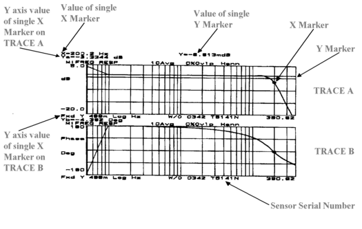
The frequency response of each component is provided as amplitude and phase plots.
When testing the instrument to confirm that it meets its design specification, the range of frequencies used are concentrated over about 3 decades (i.e. 1000 : 1) of excitation frequencies. Consequently, the frequency plots of each component are provided in normalised form. Each plot marks the frequency cut-off value (often quoted as “–3dB” or “half-power” point).
Güralp Systems performs frequency response tests on every sensor at the time of manufacture. All records are archived for future reference.
5.2.1 The sensor transfer function
Most users of seismometers find it convenient to consider the sensor as a “black box”, which produces an output signal V from a measured input x. So long as the relationship between V and x is known, the details of the internal mechanics and electronics can be disregarded. This relationship, given in terms of the Laplace variable s, takes the form
( V / x ) (s) = G × A × H (s)
In this equation
G is the acceleration output sensitivity (gain constant) of the instrument. This relates the actual output to the desired input over the flat portion of the frequency response.
A is a constant which is evaluated so that A × H (s) is dimensionless and has a value of 1 over the flat portion of the frequency response. In practice, it is possible to design a system transfer function with a very wide-range flat frequency response.
The normalising constant A is calculated at a normalising frequency value fm = 1 Hz, with s = j fm, where j = √–1.
H (s) is the transfer function of the sensor, which can be expressed in factored form:
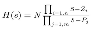
In this equation zn are the roots of the numerator polynomial, giving the zeros of the transfer function, and pm are the roots of the denominator polynomial giving the poles of the transfer function.
In the calibration pack, G is the sensitivity given for each component on the first page, whilst the roots zn and pm, together with the normalising factor A, are given in the Poles and Zeros table. The poles and zeros given are measured directly at Güralp Systems' factory using a spectrum analyser. Transfer functions for the vertical and horizontal sensors may be provided separately.