Chapter 6. Calibration information
Every CMG-5T is supplied with a comprehensive calibration pack detailing the characteristics of the sensor.
6.1 Calibration sheet
The calibration sheet provides the measured acceleration responsivities over the flat portion of the sensor frequency response, in units of volts per metre per second squared (V/ms-2). Because the sensor produces outputs in differential form (also known as push-pull or balanced output), the signal received from the instrument by a recording system with a differential input will be twice the true value. For example, the calibration sheet may give the acceleration responsivity as “2 × 0.50 V/ms-2, indicating that this factor of 2 was not included in the value given.
Caution: You must never ground any of the differential outputs. If you are connecting to a single-input recording system, you should use the signal ground line as the return line.
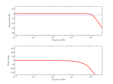
6.2 Poles and zeroes
The poles and zeroes table describes the frequency response of the sensor. If required, you can use the poles and zeroes to derive the true ground motion mathematically from the signal received at the sensor. The 5T is designed to provide a flat response (to within 3dB) over its passband. For example, the following curve describes the frequency response of a 100 Hz sensor: