Chapter 7. Inside the DM24
7.1 State of health information
The DM24 outputs diagnostic information in a status stream. This is a special GCF stream whose name ends in 00.
Status streams can take two different forms, depending on the current transmission mode:
In FILING mode, a short heartbeat message summarizing the current status is transmitted regularly at a configurable interval of between 10 seconds and a few minutes. The heartbeat message lets clients know that the digitiser is still operational, even though it is not sending data. For example, if you connect a PC running Scream! to an autonomous station over a dial-up link, Scream! can automatically download recorded data: this is made possible by the heartbeat message, which tells Scream! that the data exist.
In all other modes, status messages are output continuously, in GCF blocks. When each block is full, it is transmitted from the DATA OUT port with the rest of the data.
7.1.1 Heartbeat messages
These are output at regular intervals, and always have the same format. Older digitisers may not include all the lines described here.
64MB Flash File buffer : 65,520 Blocks Written 65,520 Unread 16 Free
Latest data [392] PLPGG SBHYX2 2006 1 18 14:55:57
Oldest data [400] PLPGG SBHYN4 2005 11 30 06:47:38
# 22 2006 1 18 14:48:36 No File Last Event
2006 1 18 14:56:15 1 MicroSeconds Fast Freq error 0 e-9 Auto 3D [-4]
PLPGG SBHY00 CMG-3T
Boot Log : 143 Power cycles 294 Watchdog resets
Last boot 2006 1 12 16:18:57 2006 1 17 17:15:14
2006 1 18 14:56:15 External supply : 13.0V Temperature 24.68'C
2006 1 18 14:56:15 Mass positions -486 -300 -424
7.1.1.1 Flash memory usage
The first three lines describe the internal Flash memory. First, the overall usage is described:
64MB Flash File buffer : 65,520 Blocks Written 65,520 Unread 16 Free
Here, a 64 Mb Flash memory store contains 65,520 data blocks, of which none have already been downloaded. This leaves 16 blocks of free space, since each block is exactly 1Kb long, and (65,520 + 16) × 1 Kb = 65,536 Kb = 64 Mb.
Latest data [392] PLPGG SBHYX2 2006 1 18 14:55:57
Oldest data [400] PLPGG SBHYN4 2005 11 30 06:47:38
These two lines show the date and time of the oldest and newest data in the buffer, together with the System ID (PLPGG) and the Stream IDs (SBHYX2 and SBHYN4) of the corresponding data stream.
7.1.1.2 Triggered events
# 15 Filed @ 64,167 PLPGG SBHYZG 2006 1 5 10:31:30 Last Event
This line gives the date and time of the last trigger, together with its System ID and Stream ID as above. Also given is the event sequence number (15, here) as used by the EVENTSLIST command, and the position in the buffer where data from the event begin.
If a trigger has occurred, but no data were output (e.g. because the digitiser was in DIRECT transmission mode), the digitiser will report
# 22 2006 1 18 14:48:36 No File Last Event
7.1.1.3 GPS
The next line describes the current status of the GPS system. When the digitiser is first powered up, the message will be something like
2005 8 10 12:35:00 GPS control OFF Auto 3-D [-5 Not sync'd]
The message GPS control OFF denotes that the clock is not yet being controlled by the GPS. Owing to noise purposely injected into the GPS timing stream, the GPS time cannot be directly used to synchronize the clock. Instead, the digitiser maintains a rolling average of time measurements, and uses this to apply corrections to the clock so that it remains accurate over a long period.
The Auto 3-D message denotes that the signal is strong enough to obtain a full 3-dimensional GPS fix. If the signal is weak, or there are too few satellites visible to the receiver, you may see Auto 2-D here. If the signal is too weak to obtain a fix, No FIX will be displayed.
After a short time, the message will change to
2005 8 10 12:36:00 GPS Control settling Auto 3-D [-5 Not sync'd]
Eventually, the GPS control system will be able to synchronize the internal clock, and the message will change to
2005 8 10 12:38:01 GPS Control settling Auto 3-D [-4]
2005 8 10 12:41:01 326 MicroSeconds Slow Freq error -7 e-9 Auto 3-D [-4]
The system is now reporting the current offset of the internal clock from GPS time (whether slow or fast), and the current frequency error. It will now continuously adjust the internal clock for as long as the GPS is powered up.
If you have chosen to save energy by enabling GPS power cycling, the DM24 will switch off the GPS once a satisfactory fix is obtained, and begin free-running on the internal clock. Whilst this is happening, the line will report
2005 8 10 17:06:27 GPS switched Off
7.1.1.4 Boot status
PLPGG SBHY00 CMG-3T
Boot Log : 143 Power cycles 294 Watchdog resets
Last boot 2006 1 12 16:18:57 2006 1 17 17:15:14
These three lines repeat information from the last re-boot:
in the first, the System ID, the Stream ID of the status stream, and the current Sensor Type;
in the second, the number of times the digitiser has been power cycled, and the number of times it has been reset without power cycling (e.g. by a re-boot after reconfiguring the module: a “soft” reset); and
in the third, the date and time of the last power cycle and of the last soft reset.
7.1.1.5 Environmental measurements
2006 1 18 14:56:15 External supply : 13.0V Temperature 24.68'C
The next line displays the current state of the DM24's power supply, and its internal temperature.
7.1.1.6 Mass positions
2006 1 18 14:56:15 Mass positions -486 -300 -424
The final line provides the instantaneous mass positions reported by the sensor at the time given.
7.1.2 Status blocks in continuous mode
In continuous mode, each status block contains a number of single-line messages:
2006 1 18 14:40:00 o/s= 90 drift= 0 pwm= 8187 Auto 3D
2006 1 18 14:41:00 o/s= 90 drift= 0 pwm= 8187 Auto 3D
2006 1 18 14:42:00 o/s= 90 drift= 0 pwm= 8187 Auto 3D
2006 1 18 14:43:00 o/s= 78 drift= -12 pwm= 8188 Auto 2D
2006 1 18 14:44:00 o/s= 89 drift= 11 pwm= 8188 Auto 3D
2006 1 18 14:45:00 o/s= 94 drift= 5 pwm= 8188 Auto 3D
2006 1 18 14:45:00 External supply : 13.0V Temperature 24.62'C
2006 1 18 14:46:00 o/s= 148 drift= 54 pwm= 8188 Auto 3D
2006 1 18 14:47:00 o/s= 174 drift= 26 pwm= 8188 Auto 3D
2006 1 18 14:48:00 o/s= 211 drift= 37 pwm= 8188 Auto 3D
2006 1 18 14:48:36 SOFTWARE Trigger : Trigger# 22
2006 1 18 14:49:00 o/s= 263 drift= 52 pwm= 8187 Auto 3D
2006 1 18 14:49:10 End of Trigger
The messages appear in the order they are generated by the different software modules inside the digitiser.
7.1.2.1 GPS status messages
The status of the attached GPS receiver is reported every minute:
2006 1 18 14:47:00 o/s= 174 drift= 26 pwm= 8188 Auto 3-D
In this line:
o/s gives the current offset of the internal clock from GPS time, in arbitrary internal units;
drift is the difference between the current o/s and the last, which gives an indication of the level of drift;
pwm, or Pulse Width Modulation, is the feedback control parameter;
Auto 3-D denotes that enough GPS satellites are currently visible to obtain a full 3D fix. If, instead, No Fix is displayed, the GPS received has not (yet) been able to obtain a satisfactory fix. If Missing PPS is displayed in this field, the digitiser has received fewer than 60 pulses on the 1pps (pulse per second) line in the last minute. You will see at least one Missing PPS message in the first minute of operation.
Every 20 minutes, at 10, 30 and 50 minutes past the hour, the GPS synchronization status is displayed. This line has the same format as the GPS line in the heartbeat message, e.g.
2005 8 10 12:41:01 326 MicroSeconds Slow Freq error -7 e-9 Auto 3-D [-4]
Finally, every hour, the DM24 displays general timing and position information, including details of the visibility of GPS satellites:
2005 6 8 11:00:00 GPS Date/Time 08/06/05 11:00:00
2005 6 8 11:00:00 Auto 3-D SV#'s 4 7 13 20 23 24 25 ( 7 )
2005 6 8 11:00:00 Lat 51'21.6591N Long 001'09.8218W
SV# stands, officially, for Space Vehicle number. Each GPS satellite has it's own unique identification number, or SV#, and the list shows which are currently usable (satellite numbers 4, 7, 13, 20, 23, 24 and 25 in this example). A minimum of four is required to obtain a full 3-dimensional GPS fix.
7.1.2.2 Trigger notifications
When a trigger occurs, a message is immediately saved to the current status block. You may not see this message straight away, however, since the status block must be full before the digitiser will send it.
2006 1 18 14:48:36 SOFTWARE Trigger : Trigger# 22
The trigger type is mentioned, as well as the sequence number (for later retrieval, if necessary, using the EVENTSLIST command). When the trigger condition ends, the system reports
2006 1 18 14:49:10 End of Trigger
7.1.2.3 Environmental measurements
These are measured every 10 minutes (at 5, 15, 25, 35, 45 and 55 minutes past the hour), and are given in the same form as for heartbeat messages:
2006 1 18 14:45:00 External supply : 13.0V Temperature 24.62'C
7.2 GPS and Synchronisation
7.2.1 Overview
The DM24 has two internal clocks: a hardware real-time clock (RTC), which runs continuously (even when the unit is powered down) and a software clock that is used for time-stamping digitised data. The software clock uses a voltage-controlled crystal oscillator (VCXO) to provide a time reference which is stable to below 0.1 ppm.
The software clock is set from the RTC at boot-up: this is the only time that the system consults the RTC.
The software clock is normally synchronised to GPS time, as reported by an attached Güralp GPS receiver. After power-up, the output from the GPS receiver is monitored until a stable fix is obtained, at which point both clocks are synchronised to GPS time. A sophisticated algorithm then monitors the frequency and phase difference between the GPS's PPS signal and the VCXO's output and adjusts the voltage input to the VCXO so that the software clock precisely tracks the average GPS time. (Recall that GPS time includes deliberate fluctuations to reduce the instantaneous accuracy for non-military users.)
If the GPS signal becomes too weak to use or if the receiver is deliberately powered down to reduce the power consumption, the software clock will continue to run with the same VCXO setting until a stable GPS signal is received again. At this point, the software clock will normally be slewed to bring it back into precise alignment with GPS time. If the difference between GPS time and the software clock after a period of free-running is too large, a step-change is performed and both clocks are re-set to GPS time. This is reported in the status stream as a resynchronisation.
7.2.2 Leap-seconds
GPS time does not include leap-seconds so the firmware in the GPS receiver performs corrections to account for the difference between GPS time and UTC. This difference is the sum of all of the leap-seconds which have occurred since the GPS epoch (January 6th, 1980) and, at the time of writing, UTC leads GPS time by 17 seconds.
The current value of the offset and the date of the next leap-second (if known) are regularly transmitted by the GPS space vehicles to the receivers. When a leap-second occurs, the receiver announces the time 23:59:60 as the extra second between 23:59:59 and 00:00:00.
If the DM24 sees this time, it recognises the leap-second and all data will be time-stamped appropriately. If for any reason, the digitiser does not receive this time - the system may, for example, be configured for GPS power-cycling and the receiver may be powered down - the digitiser will produce data with incorrect time-stamps until it can resynchronise to the GPS receiver again. If the digitiser is notified in advance about an upcoming leap-second, this situation can be avoided and the leap-second will be handled correctly even if GPS data are unavailable at the time. Güralp's newest GPS receivers - those based on the PAM7Q chip-set - will automatically notify the DM24 of upcoming leap-seconds but older receivers cannot do this.
You can manually notify a DM24 of an upcoming leap-second from the command line using the LEAPSECOND command - see section 6.4.7 for full details. This can be done at any time between the official announcement and the actual leap-second.
Upcoming leap-seconds are announced by the International Earth Rotation Service (https://www.iers.org) in their Bulletin C, to which anyone can subscribe, and also on the Güralp web-site in the Frequently-Asked Questions (Support→FAQs) section.
7.2.3 Week-number roll-over
Although the GPS system can be used to determine the date and time with extreme accuracy, the GPS satellite constellation does not actually transmit the full date to GPS receivers. Instead, a ten-bit value called "Week Number" is transmitted every thirty seconds, as part of each subframe of the "Navigation Message". It is the responsibility of the receiver to calculate the date from this value. (The time within the week is transmitted as the number of seconds since midnight on Saturday/Sunday.)
GPS week zero started at the beginning of 00:00:00 UTC on January the 6th, 1980. A ten-bit field can only hold 1024 different values so this system was never going to last forever. Indeed, week 1023 was first reached on August the 15th, 1999. The following week, the GPS satellites populated the Week Number field with a value of zero. (Because GPS time does not recognise leap-seconds, the "roll-over" from week 1023 to week zero actually took place at the end of 23:59:47 UTC on August the 21st.)
Manufacturers of GPS receivers must each choose a way to determine the correct date from the GPS Week Number. If the chosen method fails, the announced date will be 1024 weeks - about 19.7 years - in the past or, possibly, the future. One common method uses the date of the version of the firmware as a hint, which works well if the receiver is new or regularly updated. A significant problem with this method arises when the firmware is not updated: the receiver can start producing incorrect dates at the 1024-week anniversary of the firmware date. This means that problems can actually appear at any time, irrespective of the actual roll-over date.
Many significant problems were reported after the 1999 roll-over and this became known as the GPS "week-number roll-over" or "WNRO" problem. Many manufacturers had to update their receiver firmware as a result but some of these solutions were time-limited, leading to continuing problems around the April, 2019 roll-over.
The DM24 can automatically correct for receivers which report historical times as a result of this problem. If the setWNROpivot command (see section 6.4.6) is used to set a "pivot date", any dates reported by a GPS receiver which are earlier than the pivot date will be modified by repeatedly adding 1024 weeks to the reported date until a date later than the pivot date is reached. This will then be the date used for time-stamping data. Because you can set the pivot date yourself, this technique should be able to correct for any problems encountered both before and after the next roll-over, in 2038.
The following extract of a status stream shows the technique in action:
2019 7 27 23:59:00 o/s= -10263 drift= -1636 pwm= 8315 Auto 3D
2019 7 28 00:00:00 GPS Date/Time 12/12/99 00:00:00
2019 7 28 00:00:00 o/s= -9497 drift= 766 pwm= 8342 Auto 3D
2019 7 28 00:00:00 Auto 3D SV#'s 28 2 18 21 23 25 26 ( 7 )
2019 7 28 00:00:00 Lat 51'21.8502N Long 001'09.9228W Height 6m
Note how the third line starts by reporting that the system data is July 28th, 2019 but then reports that the GPS Date is December 12th, 1999. These two dates are exactly 1024 weeks apart because of the WRNO correction.
7.2.4 Multiple re-synchronisation events
In an ideal world, the digitiser would synchronise to GPS shortly after power-up and then sit happily, training its clock to GPS time with a few tiny adjustments to the VCXO control voltage to compensate for, say, thermal variations.
It would be very unusual for the GPS receiver to suddenly report a radically different time. If it does happen, the digitiser becomes sceptical and waits a whole minute, monitoring the situation without changing the internal clock. It increments an internal counter - the resync counter - to record the event and prints a message like
Clock check 1 0 Not sync'd
followed by the difference between the software clock's time and GPS time. A minute later, if the new GPS time has been stable and consistent over that minute, the digitiser will step-change its clock - a resynchronisation.
If the same thing happens again, the digitiser is even more sceptical and waits two minutes before reacting, again incrementing the resync counter. The messages are
Clock check 1 0 Not sync'd -1secs error
…
Clock check 2 0 Not sync'd -1secs error
appearing one minute apart. Again, the digitiser will resynchronise after the second message.
If the same thing keeps happening, as the resync count rises, the degree of scepticism increases to match and the digitiser waits longer and longer before resynchronising. In the example status stream below
2016 6 14 01:52:00 Clock check 8 0 Not sync'd -1secs error
2016 6 14 01:52:00 Auto 2D
2016 6 14 01:53:00 Clock check 9 0 Not sync'd -1secs error
2016 6 14 01:53:00 Auto 2D
2016 6 14 01:54:00 Clock check 10 0 Not sync'd -1secs error
2016 6 14 01:53:59 Clock sync'd to Reference =>> 2016 6 14 01:54:01 .
the process is at an advanced state. At this point, the GPS time has jumped unaccountably (compared to digitiser time) ten times since the last boot-up and the digitiser has had to resynchronise ten times to match. It has just waited ten minutes before synchronising and, if the situation were to recur, it would then wait eleven minutes.
Eventually, if the counter reaches sixteen, the digitiser stops trusting GPS time and disables resynchronisation on the grounds that something is very wrong and the user would probably prefer contiguous data with incorrect time-stamps to salami-sliced data with random time-stamps, which would be very difficult to reassemble. This condition is signified in the status stream by a message like
2015 10 18 22:56:58 Not sync'd and Re-sync Disabled!
You can reset the counter by rebooting the digitiser but it is important to diagnose and correct the underlying problem.
If the GPS receiver cannot output the correct time for a very lengthy period, the digitiser's clock may drift so far that, when a GPS lock is re-established, a synchronisation (jump) rather than a correction (slew) is appropriate. This may happen if the receiver's view of the sky is significantly obscured by, for example, vegetation.
If the crystal in the digitiser's clock has aged and deteriorated to the point where the control voltage cannot bring it into lock-step with GPS time, frequent resynchronisations may be observed. This condition can also be recognised by constant extreme values of the pwm parameter as reported in the status stream. A physical repair of the DM24 is required in this case.
Some Trimble Lassen GPS receivers would announce a time which was exactly one second out for a minute or so after power up. This is because they used a hard-coded value for the leap-second offset (see section 7.2.2) until the actual offset value was received from the satellites. When used in GPS power-cycling applications, this would cause the symptoms described (with a particularly fast escalation) because the DM24's software clock would need to jump one second backwards every receiver power-cycle and then one second forwards again each time once the offset was corrected. The solution in this case is to disable GPS power-cycling or replace the GPS receiver with a modern version.
7.3 Updating firmware
7.3.1 Updating firmware using an EAM, Affinity or NAM
The easiest way to update the digitiser firmware is by connecting it to a Platinum device, such as an EAM, Affinity or NAM. If the digitiser is part of a DM24-SxEAM or integrated *TDE instrument, this connection is already made.
The DM24 firmware can be upgraded through the web interface, using a check-box at the bottom of the data acquisition configuration page, or from the command line, with the dm24-upgrade command. Please see the platinum manual, MAN‑EAM-0003 for more details.
7.3.2 Updating firmware with Scream!
You can update the digitiser firmware using any terminal program which supports the Xmodem protocol, such as minicom, ExtraPuTTY or Scream!. If you are not using Scram, open a terminal to the output of the DM24 and key 


A terminal window opens, presenting you with the command line of the digitiser:

If you are using a different emulator, open a window as normal with the appropriate Baud rate. The communications settings should be 8-N-1 with no flow control.
Check that there is two-way communication with the digitiser by pressing Enter. The digitiser should reply with ok on a new line.
Type re-boot to reinitialize the digitiser, and confirm with y. As it is restarting, the digitiser will report its status over the terminal connection, followed by a maintenance menu:
MPE ARM ANS ROM PowerForth v6.30
ARM Serial BootStrap v1.100, 11 August 2003
Copyright (c) 2002-3 GSL, EDSL & MicroProcessor Engineering Ltd.
Port 0 38400 baud Port 1 4800 baud Port 2 38400 baud
Guralp Systems Ltd - ARM-BOOT v3.0 mgs 13/12/12 (Build _02)
System Code versions loaded :-
Current 0105:0000 Guralp Systems Ltd - DM+FW v.107 mgs 13/09/16 (Build _26)
Backup 010E:0000 Guralp Systems Ltd - DM+FW v.107 mgs 13/09/16 (Build _26)
Previous 0117:0000 Guralp Systems Ltd - DM+FW v.106 mgs 11/11/14 (Build 57w)
DSP Code :
0103:0000 dsp1091.bin loaded 2016-09-29 Default
0104:0000 dsp1091.bin loaded 2016-09-29
Command keys:
C - set real time Clock (2016 9 29 14:37:06 )
I - view/upload InfoBlock
F - run the Forth monitor
S - update System program
O - select Other system program
B - update Boot program
D - update DSP code
T - Toggle default DSP code
Q - Quit maintenance system
5 seconds to auto-start:
If you do not press a key in the next five seconds, the DM24 will start up normally. If you need more time to read the menu, press the space-bar.
The DM24 has three firmware components, which can be updated separately: the system program, the DSP code and the boot loader. Firmware releases are available on the Güralp Systems website (Select "Firmware" from the "Support" menu). If a release updates more than one component, you must update the boot loader first, followed by the system program and, finally, the DSP code.
7.3.2.1 Loading a new boot loader
Press 
The digitiser will then request a transfer using the Xmodem protocol. If you are using Scream!, a file browser window will appear automatically.

Navigate through the directories on your computer and select the file to be uploaded, or type in its full path and file name. Click 
Caution: Be sure to check beforehand that the file is a valid DM24 boot loader! Replacing the boot loader with invalid code will make it impossible to boot up the digitiser. If in any doubt, please contact Güralp Systems technical support for advice before proceeding.
Whilst the file is loading, a progress window will be displayed.
Once the file is fully transferred, the DM24 will need to reboot. It will ask you for confirmation: Press ENTER, and wait whilst the system boots.
When you are returned to the maintenance menu, you can proceed to install other firmware modules or key ENTER, which will cause the system to continue to boot.
7.3.2.2 Loading a new system program
To update the system firmware, press
Update System program
The digitiser will then request a transfer using the Xmodem protocol, as described above.
Whilst the file is loading, a progress window will be displayed. Depending on the speed of the link, it may take up to 20 minutes to transfer the firmware.
Once the file is fully transferred, the DM24 will return to the maintenance menu. Press ENTER, and wait whilst the system boots.
7.3.2.3 Loading new DSP code
Press 
Enter 0/1 to select DSP code to update
Select which of the two DSP code slots you want to overwrite, and press ENTER. The default is always 0.
Enter Filename/date – upto 31 characters
You can enter a descriptive string for the DSP code here. The DM24 will print this string at every boot-up, to remind you which version of the DSP code you are using.
Note: The EAM and other automated systems populate this with a string like:
dsp1091.bin loaded 2016-09-23
When you press ENTER, the digitiser will then request a transfer using the Xmodem protocol, as described above.
7.4 Setting up external triggering
Güralp digitisers and digital instruments can be supplied with external triggering capabilities installed. The external trigger system is designed for maximum flexibility: you can trigger other digitisers or your own equipment using built-in relays, or any equipment may be used as a trigger source. In addition, a trigger circuit can link together any number of digitisers so that they trigger simultaneously when they receive a signal.
7.4.1 Overview
The digitiser or digital instrument has two internal components related to triggering.
The trigger generator runs the triggering algorithm and determines whether a trigger has occurred. If external trigger output has been enabled, the trigger generator also operates a relay which connects the two Trigger Out pins of the DATA OUT port. These are normally pins E and F.
The Trigger Out pins are only connected whilst the generator is active. This does not include any pre-trigger or post-trigger period, which is dealt with by the trigger receiver. A trigger signal may be as short as one second.
The trigger receiver acts upon trigger signals: normally, by recording additional data streams. The receiver will always start recording if the trigger generator produces a signal. If external trigger input has been enabled, the receiver will also act on a logic signal received on the Trigger In pin of the DATA OUT port.
Any signal between +3 and +30 V referenced to power ground (pin A) can be used. The instrument's own power supply (pin B) could be connected via a relay to supply this signal, for example.
The Trigger Out pins are not connected if you provide a Trigger In voltage. The instrument must trigger itself for the relay to switch. This arrangement prevents any trigger loops from occurring.
The diagrams on this page show the additional connections you will need to make. Pins A and B, and the data pins, should be connected to your power and data systems as normal.
7.4.2 Triggering your own equipment
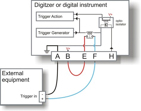
If your equipment can trigger from 24 V DC, the simplest arrangement is to use the voltage across the sensor's power supply as a trigger.
Connect the ground pin A to your equipment's trigger return line. If your equipment does not have a separate trigger return line, consult its documentation for how to apply trigger voltages. Güralp digitisers use the power ground line as a trigger return. (The diagram above does not show the power supply to either the sensor or the triggered equipment: only the triggering system is shown).
Because a trigger signal may last for only a short time, inserting pins E and F directly into your equipment's power circuit is not normally advisable. Ideally, the equipment should be continuously powered and listening on dedicated trigger input lines. If this is not possible, it may be enough to build a control circuit with a time-out period, which supplies your equipment with power for a suitable minimum length of time whenever pins E and F are connected.
The digitiser cannot anticipate a trigger. Pre-trigger recording is achieved using a continuously-updated buffer of the most recent data. Any external equipment must have its own buffering capabilities if you need pre-trigger data.
Connect pin B to pin E, and pin F to your equipment's trigger signal input.
Connect the remaining pins as normal.
If your equipment needs a different voltage, you will need to provide a separate voltage source for the triggering system. Be careful not to connect two power supplies together. The instrument's power supply can be protected by inserting a diode from pin B to pin E (see below).
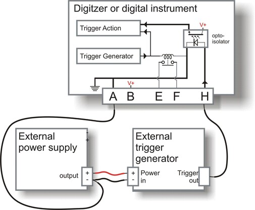
7.4.3 Using an external trigger source
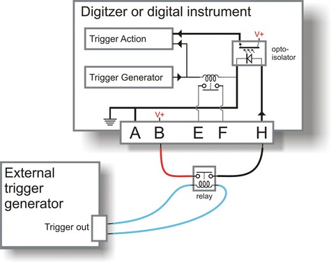
To trigger an instrument from an external source through a relay:
Connect a the normally-open switch contacts of a suitable relay between pins B and H, with the coil connected to your generator so that pins B and H are connected when a trigger occurs.
The relay allows you to power the external generator from any source. This includes the instrument's own power supply at pins A and B, if it is suitable.
Connect the other pins as normal.
If you prefer, you can use a separate power source for your trigger generator. However, because pin H is referenced to power ground, the external power supply must share a common ground with that of the digitiser, so you should connect the power supply ground to pin A.
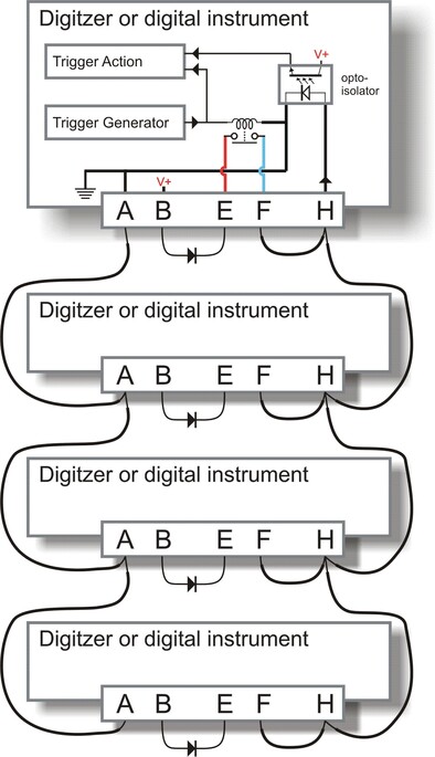
7.4.4 Triggering several Güralp instruments simultaneously
A common use of the external triggering feature is to ensure that all instruments in an array trigger at the same time. This can be achieved with the wiring layout below. With this arrangement, any instrument can generate a trigger, which will be passed on to all the instruments in the array.
For each instrument:
pin A is connected to a common ground;
pin B is connected to the instrument's power supply as normal and also to pin E through a diode (an IN4001 is suitable);
pins F and H are connected to each other and to a common trigger line; and
the remaining data pins are connected to your recording equipment as normal.
The diode at pin E is important, because if two instruments generate a trigger simultaneously, their power supplies will both be connected via the internal relay contacts to the common trigger line on pins H, and hence connected together. This can cause considerable current flow with consequent risk of fire, as well as severe damage to equipment and cables.
In the case where a single power supply is used to power all of the equipment, this is not an issue and pin E should be connected directly to pin B on all units. Pin B should then also be connected to the power supply's positive terminal.
The more common case, where each unit has it's own power supply, is shown below. Power supply wiring is omitted for the sake of clarity but note that all the power supply's ground terminals will be connected together via the links between pin A on each unit. The power supplies must, therefore, have floating outputs or grounded negative terminals.
7.5 Technical details
Internally, DM24 digitisers are structured as shown in the following diagram, where each box represents a separate internal subsystem.

The system is designed around a low power, high performance ARM microprocessor. This is a 32-bit processor with a large address space for data storage and manipulation. It also includes many integrated functions such as multiple timers and serial I/O ports. In addition, the system contains a Cirrus Logic CS5376 digital filtering chip-set and TMS320VC33 digital signal processor (DSP). The CS5376 provides data to the DSP at 2,000 samples per second, triggered by timing signals from the ARM processor. The DSP can control all 5 ADCs and process the data in real time.
An important feature of the system design is its ability to synchronise the sampling of the analogue to digital converter to an external time reference. This way, data samples are accurately time stamped at source. To keep sampling accurately in step with UTC, the microprocessor's time-base is synchronized to an external reference, derived from GPS or, in larger arrays, to a centrally-transmitted time reference. Sharing a time reference avoids the cost and power consumption of multiple GPS receivers and, since it only involves sending 2 characters per second, it can utilise a low bandwidth link.
To achieve the high degree of timing precision required for a 24-bit digitiser system, the microprocessor time-base is run from a precision voltage controlled oscillator. On-board software keeps this oscillator tuned to the external reference so that its frequency is accurately set and maintained through changes in temperature or ageing. Once the system has stabilised, the control is sufficiently accurate to maintain precision sampling for several days without an external reference. The system also automatically compensates for the pure time delay introduced by the digital filtering/decimation processes in the DSP.
The DSP software consists of 6 cascaded programmable filter/decimation stages, which allow you to select multiple data output rates simultaneously. Each stage can be set individually for decimation factors of 2, 4, or 5. Data can be output at up to four different rates. For example, a system can be configured to provide data at 200, 50, and 10 samples per second, covering the whole of the seismological broad band range. The configuration of the DSP is programmable in the field via the host ARM microprocessor.
The DM24's interface to the world is via its serial ports. Port 0 is used for GCF data output. Port 1 is the NMEA input from the GPS receiver and Port 2 is the system's console. The console can be used as a command line interface without interrupting data flow via Port 0.