Chapter 12. Transmitting Data
Received data may be re-transmitted in near real time in one or more of a number of different formats. By default, a GCF Scream server and GDI Link transmitter are instantiated, both configured to forward all received data. Any other desired transmitters must be configured and enabled before use.
The following transmission services are currently available:
GCF BRP serial server - see section 12.1.2
GCF BRP network server - see section 12.1.3
GCF Scream network server - see section 12.1.4
SEEDlink - see section 12.2
EarthWorm – see section 12.3
CD1.1 - this is covered in a separate manual, MAN-EAM-1100.
GSMS: Güralp Seismic Monitoring System - see section 12.4
QSCD: Quick Seismic Characteristic Data - see section 12.5
WIN sender - see section 12.6
12.1 GCF
Three GCF servers are available, a GCF BRP serial server, which can output data over any available serial port, a GCF BRP network server and a GCF Scream network server. All of these take their input from one or more GCF compressors. These servers are described in the next section.
12.1.1 The GCF compressor
The GCF compressor, gdi2gcf, converts from GDI to GCF format. It provides channel filtering, channel name mapping and data buffering for the gdi-record service, which writes GCF files to mass storage device.
One instance of gdi2gcf is present in the default configuration. Additional instances may be created as required. This will be necessary if you have different channel filtering requirements for, say, recording and transmitting or if you need different transmitters to send different sets of channels. The configuration page for every transmitter has, in the “Expert mode” options, a drop-down menu which allows the operator to select which compressor instance to use for its input. The gdi-record configuration page has a similar facility.
Instances of the GCF compressor are “dependant services”, meaning that they do not need to be (and should not be) configured to start automatically when the system boots. They will be started whenever a client service, such as a connected transmitter, starts.
To configure a GCF compressor on the acquisition module, select
Configuration → Services → GCF
or
Configuration → All Options → System services → GCF
To configure an instance from the command line, start gconfig and select “System services” from the top level menu.
Select the “gdi2gcf - GCF compressor” link. The screen shows a list of all GCF compressor instances that have been configured:
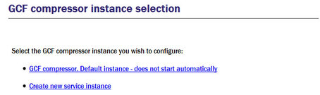
To configure any existing instance, click on its link. To configure an additional gdi2gcf instance, select “Create new service instance”. The resulting screen allows you to configure the parameters of the selected instance.
12.1.1.1 Configurable parameters in simple mode
The configurable parameters for the GCF compressor in simple mode have two tabbed pages: General and Channels.
General
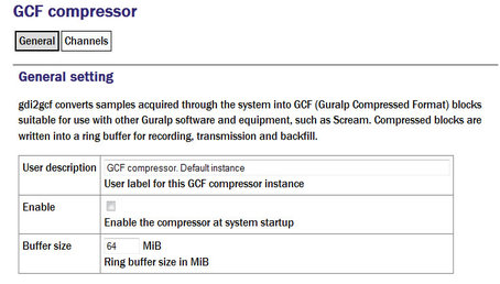
User description: Sets the name of the service. If multiple instances are created, this can be set to meaningful names for the data that each will be handling.
Enable: Causes this service to start automatically when the system is re-booted. If this check-box is cleared, the service will need to be started manually (from the “Control” → “Services” menu)
Delete: Causes the configuration for this instance to be removed from the system when the form is submitted.
Buffer size: GCF data from the compressor are held in a ring buffer from which all client services, such as GCF transmitters or the mass storage device recorder, read. The number in the field determines both how long a communication link can be down before data are lost and the time interval between “flush to disk” operations (which can affect power consumption).
The next section of this page, shown overleaf, contains a drop-down menu and a table which allow the operator to control which channels are transmitted and, optionally, renaming them.
Channels
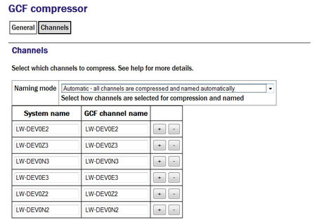
Naming mode: The drop-down menu offers three choices:
Automatic - all channels are compressed and named automatically: Offers no filtering and uses the system-generated names for each channel as forwarded by gdi-base.
Semi-automatic - all channels are compressed, names may be mapped below: One or more of the channels may be renamed by adding entries to the mapping table. If you wish to use this mode, it may be useful first to run the system in automatic mode for a short while: this will populate the mapping table with an entry for each currently known channel, which can serve as the basis for your own mapping table.
Manual - only channels named below are compressed: Offers both channel filtering and name mapping. If you wish to use this mode, it may be useful first to run the system in automatic mode for a short while to populate the mapping table with an entry for each currently known channel; this can serve as the basis for your own mapping table.
Clicking the  button on any row will open a new row. In the same way, rows can be deleted by clicking the corresponding
  button.
Deleted channels will be transmitted unmapped in “Semi-automatic” mode and not transmitted in “Manual” mode.
12.1.1.2 Configurable parameters in expert mode
The following additional parameters are available in expert mode:
Advanced
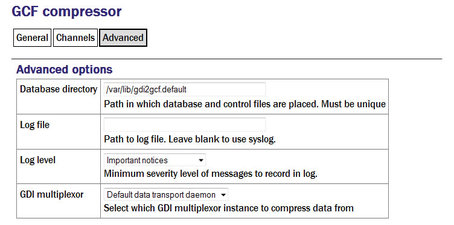
Database directory: Can be used to control the location of the ring-buffer and associated files. In most configurations, the default location is adequate but if, for example, a very large ring-buffer is desired and the optional extra flash memory module is fitted, it may be desirable to use the extra memory for this purpose. To do this, enter into this field the path to a unique directory under /media/flash_module.
Log file: It may sometimes be desirable, for debugging purposes, to separate log messages for this transmitter from the standard system log. The text field can be populated with a path name which will then be used for dedicated logging. If left blank, logging occurs (via the standard Linux syslog facility) to /var/log/messages.
Log level: The drop-down menu controls the level of detail present in log messages. Not all of the standard syslog logging levels are available. The menu offers a choice (in order of decreasing detail) of:
Debugging information
Informational messages
Important notices
Warnings
GDI multiplexer: In most configurations, all data for all compressors are taken from a single multiplexor, as described in section 6.1. For more complex configurations, it is possible to configure multiple multiplexers, each with their own set of input and output services. In these situations, the drop-down menu can be used to select a multiplexer instance with which to associate this compressor. The menu offers a list of currently configured multiplexers.
12.1.2 GCF BRP Serial Server
The GCF BRP serial server transmits Güralp Compressed Format (GCF) data using the Block Recovery Protocol (BRP) over any available serial port.
To configure a GCF BRP serial server from the web interface, select:
Configuration → Serial ports
or
Configuration → All options → Serial ports
To configure a GCF BRP serial server from the command line, start gconfig and select Serial ports from the top-level menu.
Now select the serial port over which you wish to transmit GCF.
Port function: Select GCF out. Outbound GCF data transmission from the drop-down menu.
Port speed: Choose the required Baud rate from the drop-down menu.
Now select the GCF output settings link from the list at the bottom of the page. The next screen allows you to configure the GCF BRP serial server instance which will run on the previously selected port. The screen illustrated here is for an instance running on the DATA OUT port: the screens for other serial ports are practically identical.
12.1.2.1 Configurable parameters in simple mode
The configurable parameters for the GCF output settings in simple mode have two tabbed pages: General and Filtering.
General
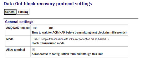
ACK/NAK timeout: Populated with an integer value which specifies the number of milliseconds the server should wait for an acknowledgement packet before transmitting the next block.
Mode: The drop-down menu controls the BRP transmission mode of the server. At present, the only available choice is “Direct - simple transmission with link error correction but no backfill”. Future implementations will offer additional options.
Allow terminal: If checked, the server will allow remote clients access to the source digitiser's command line for configuration purposes.
Filtering
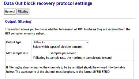
Output type: The drop-down menu offers a choice of:
All blocks - filtering by block type is disabled
Only status blocks - no data blocks are transmitted
Only blocks below a certain sample rate - the threshold (inclusive) rate is specified in the following text field.
Only blocks matching a list of channel names - offering the highest granularity of control.
Max sample rate: If the output type is set to Only blocks below a certain sample rate, the text field is used to specify the inclusive threshold, above which data are not transmitted.
If the Output type field is set to Only blocks matching a list of channel names, the channel names must be specified in the channel name table:

12.1.2.2 Configurable parameters in expert mode
The following additional configuration parameters in expert mode
Advanced
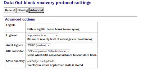
Log file: It may sometimes be desirable, for debugging purposes, to separate log messages for this transmitter from the standard system log. The text field can be populated with a path name which will then be used for dedicated logging. If left blank, logging occurs (via the standard Linux syslog facility) to /var/log/messages.
Log level: The drop-down menu controls the level of detail present in log messages, whether to syslog or to a dedicated log file. Not all of the standard syslog logging levels are available. The menu offers a choice (in order of decreasing detail) of:
Debugging information;
Informational messages;
Important notices; or
Warnings
Audit log size: The GCF BRP serial sender keeps its own audit log, independent from the system log. The contents of this log are available using the “GCF Audit Log viewer” facility as described in section 14.4.5. The amount of data retained is controlled by the drop-down menu, where the choices are:
64Kib (small)
256Kib (medium)
2MiB (large)
16MiB (huge)
GDI multiplexer: In most configurations, all data for all transmitters is taken from a single multiplexor, as described in section 6.1. For more complex configurations, it is possible to configure multiple multiplexers, each with their own set of input and output services. In these situations, the drop-down menu can be used to select a multiplexer instance with which to associate this transmitter. The menu offers a list of currently configured multiplexers.
State directory: The GCF BRP protocol requires the transmitter to store some state information. By default, this is held in the directory /var/lib/gcf-out-brp.PPP where PPP is the port name. The text field can be changed to cause this information to be stored elsewhere (typically on another device). This may be useful for managing storage utilisation in complex configurations.
12.1.3 GCF BRP Network Server
The GCF BRP network server transmits Güralp Compressed Format (GCF) data using the Block Recovery Protocol (BRP) over an Ethernet network.
To configure a GCF BRP network server from the web interface, select:
Configuration → Services → GCF
or
Configuration → All options → System services → GCF
To configure a GCF BRP network server from the command line, start gconfig and select “System services” from the menu.
Now select “gcf-out-brp”. The screen shows a list of all GCF BRP configured server instances.
You can reconfigure any existing service by clicking on its menu entry. To configure a new GCF BRP server instance, select “Create new service instance.”
12.1.3.1 Configurable parameters in simple mode
The configurable parameters for the GCF BRP network server have four tabbed pages in simple mode: General, Network, Protocol and Filter.
General
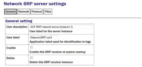
User description: Used to rename the service in configuration menus to something more indicative of its function.
User label: Used to provide a shorter but still potentially more useful name for use in log files.
Enable: Causes this service to start automatically when the system is re-booted if checked. If this check-box is cleared, the service will need to be started manually (from the “Control” → “Services” menu)
Delete: Causes the configuration for this instance to be removed from the system if ticked when the form is submitted.
Network
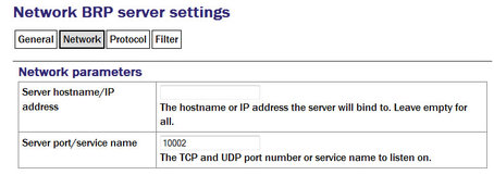
Server hostname/IP address: Used to restrict the server to listen for incoming connection requests only via particular network interfaces. If multiple interfaces or addresses are configured for this system, entering the IP address or associated hostname of one of them prevents connection attempts made to all other addresses. If left blank, connection requests will be considered from all interfaces.
Server port/service name: Must be populated with the service name or port number on which it will listen for incoming connections. This must not be used by any other service on this system.
Protocol
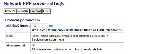
ACK/NAK timeout: Should be populated with an integer value which specifies the number of milliseconds the server should wait for an acknowledgement packet before transmitting the next block.
Mode: The drop-down menu controls the BRP transmission mode of the server. At present, the only available choice is “Direct - simple transmission with link error correction but no backfill”. Future implementations will offer additional options.
Filter
The “Output filtering” section allows the operator to control which data are transmitted, selecting by block type, sample rate or channel name.
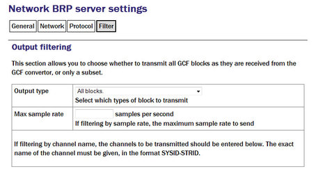
Output type: The drop-down menu offers a choice of:
All blocks - filtering by block type is disabled
Only status blocks - no data blocks are transmitted
Only blocks below a certain sample rate - the threshold (inclusive) rate is specified in the following text field.
Only blocks matching a list of channel names - offering the highest granularity of control.
Max sample rate: If the output type is set to Only blocks below a certain sample rate, the text field is used to specify the inclusive threshold, above which data are not transmitted.
If the Output type field is set to Only blocks matching a list of channel names, the channel names must be specified in the channel name table:
Channels should be specified by giving their system ID and their stream ID, separated by a hyphen ('-').
Clicking the button on any row will open a new row. In the same way, rows can be deleted by clicking the corresponding button.
If the form is submitted when the table is full, extra blank lines are appended.
12.1.3.2 Configurable parameters in expert mode
The following additional configuration parameters are available by clicking the  button at the bottom of the form and selecting the 'Advanced' tab.
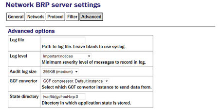
Log file: It may sometimes be desirable, for debugging purposes, to separate log messages for this transmitter from the standard system log. The text field can be populated with a path name which will then be used for dedicated logging. If left blank, logging occurs (via the standard Linux syslog facility) to /var/log/messages.
Log level: The drop-down menu controls the level of detail present in log messages, whether to syslog or to a dedicated log file. Not all of the standard syslog logging levels are available. The menu offers a choice (in order of decreasing detail) of:
Debugging information
Informational messages
Important notices
Warnings
Audit log size: The GCF BRP sender keeps its own audit log, independent from the system log. The contents of this log are available using the “GCF Audit Log viewer” facility as described in section 14.4.5. The amount of data retained is controlled by the drop-down menu, where the choices are:
64Kib (small)
256Kib (medium)
2MiB (large)
16MiB (huge)
Debug port: It is possible to copy all incoming data, verbatim, to a network port, which can be specified in the text field. This is an advanced debugging technique which is beyond the scope of this manual.
GDI multiplexer: In most configurations, all data for all transmitters is taken from a single multiplexor, as described in section 6.1. For more complex configurations, it is possible to configure multiple multiplexers, each with their own set of input and output services. In these situations, the drop-down menu can be used to select a multiplexer instance with which to associate this transmitter. The menu offers a list of currently configured multiplexers.
State directory: The GCF BRP protocol requires the transmitter to store some state information. By default, this is held in the directory /var/lib/gcf-out-brp.n where n is the instance number (counting from zero for the first instance). The text field can be used to cause this information to be stored elsewhere: typically on another device. This may be useful for managing storage utilisation in complex configurations.
12.1.4 GCF Scream Server
The GCF Scream network server transmits Güralp Compressed Format (GCF) data in the native Scream protocol over an Ethernet network.
To configure a GCF Scream network server from the web interface, select:
Data transfer/recording → Services
or
Configuration → All options → System services
To configure a GCF Scream network server from the command line, start gconfig and select “System services” from the top level menu.
Now select “gcf-out-scream” from the System Services menu. The next screen shows a list of all GCF Scream server instances that have been configured:
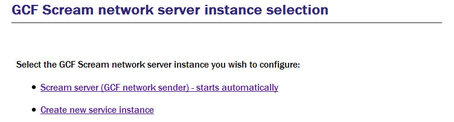
You can reconfigure any existing service by clicking on its menu entry. To configure a new GCF Scream server instance, select “Create new service instance”. The following screen allows you to configure the parameters of the service. It is a large form and is shown here in parts.
12.1.4.1 Configurable parameters in simple mode
The configurable parameters for GCF Scream network server have four tabbed pages in simple mode: General, Terminal, Push and Filter
General
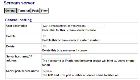
User description: Used to rename the service in configuration menus and log files to something more indicative of its function.
The first instance can neither be disabled nor deleted but, if subsequent instances are created, two additional check-boxes appear on their associated configuration menu:
Enable: Causes this service to start automatically when the system is re-booted. If this check-box is cleared, the service will need to be started manually (from the “Control” → “Services” menu)
Delete: Causes the configuration for this instance to be removed from the system when the form is submitted.
Server hostname/IP address: Used to restrict the server to listen for incoming connection requests only via particular network interfaces. If multiple interfaces or addresses are configured for this system, entering the IP address or associated hostname of one of them prevents connection attempts made to all other addresses. If left blank, connection requests will be considered from all interfaces.
Server port/service name: Must be populated with the service name or port number on which it will listen for incoming connections. This must not be used by any other service on this system.
Terminal
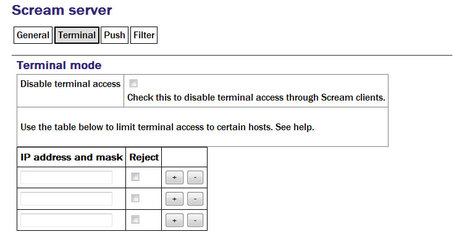
Disable terminal access: Used to prevent clients of this server from accessing the command line of the originating digitiser via the connection, allowing support for data consumers who should not be allowed to reconfigure the data sources. If this check-box is ticked, the table below can be used to either prohibit terminal access to all hosts except those listed (by ticking the relevant Reject check-boxes) or to allow access to all hosts except those lists (by leaving the relevant Reject check-boxes clear).
Push
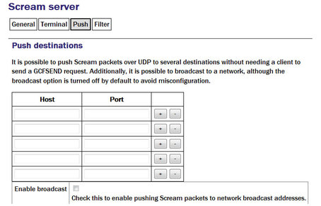
The scream server is capable of both responding to data requests from clients (PULL mode) and of sending data uninvited to remote destinations (PUSH mode). The table below is used to list any PUSH mode clients. For each, a Host must be specified as either an IP address or hostname and a Port must be given as either a service number or name.
Clicking the button on any row will open a new row. In the same way, rows can be deleted by clicking the corresponding button.
Enable broadcast: By default, the server will not send to network broadcast addresses. This behaviour can be enabled by ticking the check-box.
Filter
The “Output filtering” section allows the operator to control which data are transmitted, selecting by block type, sample rate or channel name.
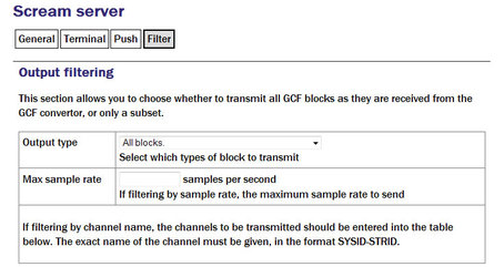
Output type: The drop-down menu offers a choice of:
All blocks - filtering by block type is disabled
Only status blocks - no data blocks are transmitted
Only blocks below a certain sample rate - the threshold (inclusive) rate is specified in the following text field.
Only blocks matching a list of channel names - offering the highest granularity of control.
Max sample rate: If the output type is set to Only blocks below a certain sample rate, the text field is used to specify the inclusive threshold, above which data are not transmitted.
If the Output type field is set to Only blocks matching a list of channel names, the channel names must be specified in the channel name table:
Channels should be specified by giving their system ID and their stream ID, separated by a hyphen ('-').
Clicking the button on any row will open a new row. In the same way, rows can be deleted by clicking the corresponding button.
12.1.4.2 Configurable parameters in expert mode
The following additional configuration parameters are in expert mode:
Advanced
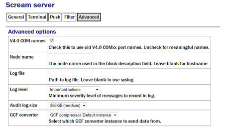
V4.0 COM names: Early versions of the Scream protocol expected all data to originate from COM ports and the port number was used to identify data sources. Version 4.5 and above of the protocol allow for a much more flexible naming scheme. The check-box can be cleared to enable advanced naming or ticked to retain compatibility with earlier versions of the protocol.
Node name: The protocol includes a description field identifying the source of each block. By default, this is set to the host name of the originating machine but it can be over-ridden by entering a value in the field.
Log file: It may sometimes be desirable, for debugging purposes, to separate log messages for this transmitter from the standard system log. The text field can be populated with a path name which will then be used for dedicated logging. If left blank, logging occurs (via the standard Linux syslog facility) to /var/log/messages.
Log level: The drop-down menu controls the level of detail present in log messages, whether to syslog or to a dedicated log file. Not all of the standard syslog logging levels are available. The menu offers a choice (in order of decreasing detail) of:
Debugging information
Informational messages
Important notices
Warnings
Audit log size: The GCF Scream sender keeps its own audit log, independent from the system log. The contents of this log are available using the “GCF Audit Log viewer” facility as described in section 14.4.5. The amount of data retained is controlled by the drop-down menu, where the choices are:
64Kib (small)
256Kib (medium)
2MiB (large)
16MiB (huge)
GDI multiplexer: In most configurations, all data for all transmitters is taken from a single multiplexor, as described in section 6.1. For more complex configurations, it is possible to configure multiple multiplexers, each with their own set of input and output services. In these situations, the drop-down menu can be used to select a multiplexer instance with which to associate this transmitter. The menu offers a list of currently configured multiplexers.
12.2 SEEDlink
The Standard for the Exchange of Earthquake Data (SEED) is an international standard format for the exchange of digital seismological data developed by the USGS and adopted as a standard by the Federation of Digital Broad-Band Seismograph Networks (FDSN). MiniSEED is a stripped-down version of SEED, which only contains waveform data, without the station and channel metadata that are included in full SEED.
Incoming data (in any format other than CD1.1) is converted first into GDI format. In order to transmit SEEDlink data or record it to mass storage device, it must be converted into miniSEED format; this is done by the gdi2miniseed module, known as the GDI Mini-SEED compressor.
12.2.1 The GDI Mini-SEED compressor
A default instance of the GDI Mini-SEED compressor is provided. Further instances can be created if required for complex implementations. Although the default instance is not set to start automatically, it is a necessary prerequisite for both SEEDlink transmission and recording, so it will be started as a dependant service when required.
To configure a GDI Mini-SEED compressor from the web interface, select:
Configuration → Services → Mini-SEED
or
Configuration → All options → System services → Mini-SEED
To configure a GDI Mini-SEED compressor from the command line, start gconfig and select “System services” from the top level menu.
Now select gdi2miniseed - Mini-SEED compressor.
The screen shows a list of all Mini-SEED compressor instances that have been configured:
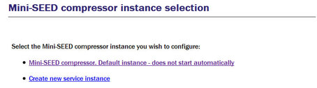
Although the default instance is marked as “does not start automatically”, it will be started if a dependant service is started.
You can reconfigure any existing compressor by clicking on its menu entry. To configure a new Mini-SEED compressor instance, select Create new service instance. The following screen allows you to configure the parameters of the compressor. The first part of the screen is shown below.
12.2.1.1 Configurable parameters in simple mode
The configurable parameters for the Mini-SEED compressor have two tabbed pages in simple mode: General and Channels.
General
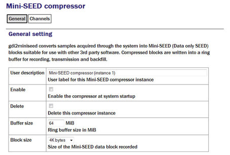
User description: Set to a meaningful name for the data the compressor will handle.
Enable/Disable: The server can be enabled or disabled at boot-up.
Buffer size: Data converted by the compressor are written to a ring-buffer which is read by both the miniSeed recorder and the SEEDlink transmitter. The size of this buffer can be set using the text entry field, which accepts an integer number of mebibytes. Records can be extracted from this buffer to a file: see section 14.4.4 for more details.
Block size: The SEED block size is set in the compressor and can not be changed by subsequent software modules. This has the important implication that, if data are to be transmitted using the SEEDlink server, this parameter must be set to 512 bytes. The size is controlled by the drop-down menu and the possible choices range from 256 bytes to 8K bytes, doubling at each step. The default value is 4K bytes: this is chosen as the optimal for mass storage device recording.
Channels
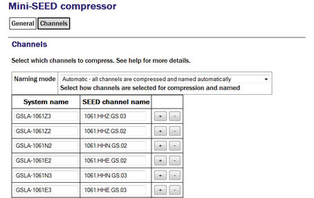
The Naming mode drop-down menu offers three choices:
“Automatic - all channels are compressed and named automatically”. This mode offers no filtering and provides system-generated names for each channel forwarded by gdi-base.
“Semi-automatic - all channels are compressed, names may be mapped below”. In this mode, one or more of the channels may be renamed by adding entries to the mapping table. If you wish to use this mode, it may be useful first to run the system in automatic mode for a short while: this will populate the mapping table with an entry for each currently known channel, which can serve as the basis for your own mapping table.
“Manual - only channels named below are compressed”. This mode offers both channel filtering and name mapping. If you wish to use this mode, it may be useful first to run the system in automatic mode for a short while: this will populate the mapping table with an entry for each currently known channel, which can serve as the basis for your own mapping table.
Clicking the button on any row will open a new row. In the same way, rows can be deleted by clicking the corresponding button.
If the form is submitted when the table is full, extra blank lines are appended.
Deleted channels will be transmitted unmapped in “Semi-automatic” mode and not transmitted in “Manual” mode.
12.2.1.2 Configurable parameters in expert mode
The following additional configuration parameters are available by clicking the “Expert” button at the bottom of the form and selecting the 'Advanced' tab.
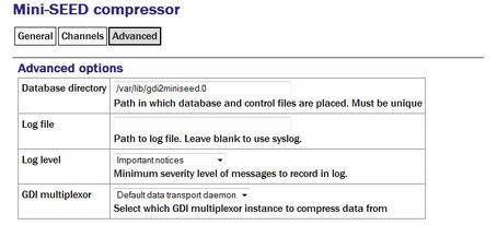
The Database directory field can be used to control the location of the ring-buffer and associated files. In most configurations, the default location is adequate but if, for example, a very large ring-buffer is desired and the optional extra flash memory module is fitted, it may be desirable to use the extra memory for this purpose. To do this, enter into this field the path to a unique directory under /media/flash_module.
Log file: It may sometimes be desirable, for debugging purposes, to separate log messages for this transmitter from the standard system log. The text field can be populated with a path name which will then be used for dedicated logging. If left blank, logging occurs (via the standard Linux syslog facility) to /var/log/messages.
Log level: The drop-down menu controls the level of detail present in log messages, whether to syslog or to a dedicated log file. Not all of the standard syslog logging levels are available. The menu offers a choice (in order of decreasing detail) of:
Debugging information
Informational messages
Important notices
Warnings
GDI multiplexer: In most configurations, all data for all transmitters is taken from a single multiplexor, as described in section 6.1. For more complex configurations, it is possible to configure multiple multiplexers, each with their own set of input and output services. In these situations, the drop-down menu can be used to select a multiplexer instance with which to associate this transmitter. The menu offers a list of currently configured multiplexers.
12.2.2 The SEEDlink server
The SEEDlink server transmits data in miniSEED format (i.e. no station/channel metadata) over the network to remote data consumers. The data are generated by a GDI Mini-SEED compressor instance.
Note: The SEEDlink server requires data in 512 byte blocks - the compressor must be reconfigured from its default setting (4 Kbytes) if the SEEDlink server is to be used: see the previous section for details.
The system will prevent you from configuring a SEEDlink server unless the chosen compressor is set to prepare 512-byte blocks. The system does not stop you from subsequently reconfiguring the compressor but, if you change the block size, the SEEDlink server will fail.
If you want to write miniSEED data with a block-size other than 512 bytes and run a SEEDlink server, you should instantiate different compressors for each.
A single SEEDlink server instance takes data from a single compressor instance and can serve multiple, simultaneous clients. If it is required to serve different channels to different clients, multiple server instances should be configured, each receiving data from a different compressor instance (the channel selection is controlled by the compressor, not the server). A server has a configured “Organization” name: if data are to appear to come from multiple organizations, multiple server instances should be configured: they can share a compressor instance if they will be serving the same channels or a number of compressor instances can be used.
To configure a SEEDlink server from the web interface, select:
Data transfer/recording → Services
or
Configuration → All options → System services
To configure a SEEDlink server from the command line, start gconfig and select “System services” from the top level menu.
Now select “seedlink-out -- SEEDlink network server” from the System Services menu. The next screen shows a list of all SEEDlink server instances that have been configured:

You can reconfigure any existing service by clicking on its menu entry. To configure a new SEEDlink server, select “Create service instance”. The following screen, shown overleaf, allows you to configure the parameters of the server.
12.2.2.1 Configurable parameters in simple mode
The configurable parameters for the SEEDlink network server are contained in a single form in simple mode:
General
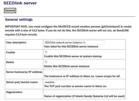
User description: Set to a meaningful name for the server data.
Enable: Causes this service to start automatically when the system is re-booted. If this check-box is cleared, the service will need to be started manually (from the “Control” → “Services” menu)
Delete: Causes the configuration for this instance to be removed from the system when the form is submitted.
Server hostname/IP address: To configure the server to listen for incoming data requests only on a specific IP address, set this (or the associated host name) in the text field. By default it will listen on all configured interfaces.
Server Port/service name: Set the port (port number or service name) that you want the server to listen on in the text field.
Organization: The server identifies itself to clients with an organization name, this should be entered into the text-field. If left blank, the value will default to “Güralp Systems Ltd”.
12.2.2.2 Configurable parameters in expert mode
The following additional configuration parameters are available by clicking the “Expert” button at the bottom of the form and selecting the 'Advanced' tab.
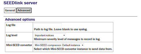
Log file: It may sometimes be desirable, for debugging purposes, to separate log messages for this transmitter from the standard system log. The text field can be populated with a path name which will then be used for dedicated logging. If left blank, logging occurs (via the standard Linux syslog facility) to /var/log/messages.
Log level: The drop-down menu controls the level of detail present in log messages, whether to syslog or to a dedicated log file. Not all of the standard syslog logging levels are available. The menu offers a choice (in order of decreasing detail) of:
Debugging information
Informational messages
Important notices
Warnings
GDI multiplexer: In most configurations, all data for all transmitters is taken from a single multiplexor, as described in section 6.1. For more complex configurations, it is possible to configure multiple multiplexers, each with their own set of input and output services. In these situations, the drop-down menu can be used to select a multiplexer instance with which to associate this transmitter. The menu offers a list of currently configured multiplexers.
12.3 EarthWorm
EarthWorm is a suite of automated earthquake processing software developed by Instrument Software Technologies, Inc. For more information, please see www.isti.com/products/earthworm.
The EarthWorm sender allows Platinum systems to send data directly to an EarthWorm installation.
To configure an EarthWorm sender from the web interface, select:
Configuration → Services → Miscellaneous
or
Configuration → All options → System services → Miscellaneous
To configure an EarthWorm sender from the command line, start gconfig and select “System services” from the top level menu.
Now select “gdi2ew -- Earthworm sender”. The screen shows a list of all EarthWorm sender instances that have been configured:
You can reconfigure any existing service by clicking on its menu entry. To configure a new EarthWorm sender, select “Create service instance”. The following screen allows you to configure the parameters of the sender.
12.3.1 Configurable parameters in simple mode
The configurable parameters for the EarthWorm sender have four tabbed pages in simple mode: General, Settings, Channels and Heartbeats.
12.3.1.1 General tab
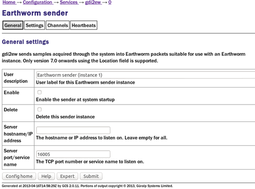
User description: This field allows the user to configure a meaningful name for this EarthWorm sender instance.
Enable: When ticked, causes this service instance to start automatically when the system is re-booted. If this check-box is cleared, the service will need to be started manually (from the “Control” → “Services” menu)
Delete: Causes the configuration for this instance to be removed from the system when the form is submitted.
Server hostname / IP address: By default, the service instance will listen for incoming connections on all available interfaces. If this field is populated with an IP address, the instance will only listen for connections addressed to the specified IP address. This option is only useful on systems with multiple IP addresses.
Server port/service name: This field specifies the port on which the service instance listens for incoming connections. The port can be specified as either a name or a number. The mapping from port names to port numbers is configured by the conventional Linux file /etc/services which can be edited from the command line if required.
12.3.1.2 Settings tab
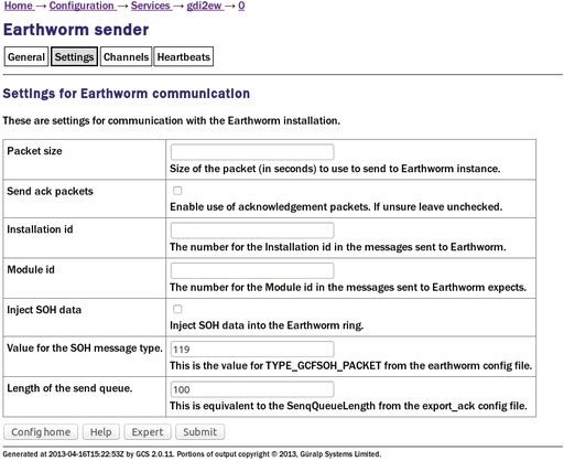
Packet size: This field controls the size of the data packets that are transmitted. The size should be specified as a duration, in seconds.
Send ack packets: This check-box, when ticked, enables the use of acknowledgement packets. These are not normally required when the connection between the client and server is reliable.
Installation id: This field allows the user to specify the installation ID that will be supplied to the EarthWorm installation.
Module id: This field allows the user to specify the module ID that will be supplied to the EarthWorm installation.
Inject SOH data: This check-box, when ticked, causes the service instance to generate special state-of-health (SoH) packets and send them to the EarthWorm installation.
Value for the SOH message type: State-of-health packets should have a distinct message type to distinguish them from seismic data packets. If the previous check-box is ticked, use this field to specify the message type. This value must match the value of TYPE-GCFSOH_PACKET in the EarthWorm configuration file.
Length of the send queue: This field controls the size of the buffer used for sending data and should match the parameter SendQueueLength in the EarthWorm export_ack configuration file.
12.3.1.3 Channels tab
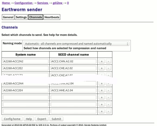
The channels tab contains a drop-down menu and a table which allow the operator to control which channels are transmitted and, optionally, rename them.
Naming mode: The drop-down menu offers three choices:
Automatic - all channels are compressed and named automatically: Offers no filtering and uses the system-generated names for each channel as forwarded by gdi-base.
Semi-automatic - all channels are compressed, names may be mapped below: One or more of the channels may be renamed by adding entries to the mapping table. If you wish to use this mode, it may be useful first to run the system in automatic mode for a short while: this will populate the mapping table with an entry for each currently known channel, which can serve as the basis for your own mapping table.
Manual - only channels named below are compressed: Offers both channel filtering and name mapping. If you wish to use this mode, it may be useful first to run the system in automatic mode for a short while to populate the mapping table with an entry for each currently known channel; this can serve as the basis for your own mapping table.
Clicking the button on any row will open a new row. In the same way, rows can be deleted by clicking the corresponding button.
Channels which do not appear in the mapping table will be transmitted unmapped in “Semi-automatic” mode and not transmitted in “Manual” mode.
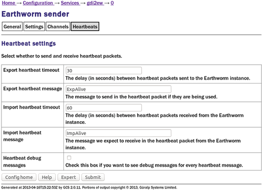
12.3.1.4 Heartbeats tab
EarthWorm has a “heart-beats” facility which can be used for monitoring connections. Heartbeats are generated both by the client and by the server. A heartbeat is a small packet sent at regular intervals so that an alert can be raised if a heartbeat packet does not arrive within a configurable time. Heartbeat packets contain configurable messages.
The following fields can be configured:
Export heartbeat timeout: This parameter controls how often this sender instance will broadcast heartbeat packets to the EarthWorm installation.
Export heartbeat message: This field allows the user to set the message contained within outgoing heartbeat packets.
Import heartbeat timeout: This parameter controls how often this sender instance should expect to receive heartbeat packets from the EarthWorm installation.
Import heartbeat message: This field allows the user to set the message that this sender instance should expect to see within incoming heartbeat packets.
Heartbeat debug messages: If this check-box is ticked, debugging messages are generated for every heartbeat packet sent, received or expected but missed.
Debugging messages will normally be written to /var/log/messages but a different file can be specified in Expert mode.
12.3.2 Configurable parameters in Expert mode
Clicking the button will display an additional tab, “Advanced”, with three extra fieds.
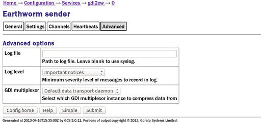
Log file: It may sometimes be desirable, for debugging purposes, to separate log messages for this sender from the standard system log. The text field can be populated with a path name which will then be used for dedicated logging. If left blank, logging occurs (via the standard Linux syslog facility) to /var/log/messages.
Log level: The drop-down menu controls the level of detail present in log messages, whether to syslog or to a dedicated log file. Not all of the standard syslog logging levels are available. The menu offers a choice (in order of decreasing detail) of:
Debugging information
Informational messages
Important notices
Warnings
GDI multiplexer: In most configurations, all data for all transmitters is taken from a single multiplexor, as described in section 6.1. For more complex configurations, it is possible to configure multiple multiplexers, each with their own set of input and output services. In these situations, the drop-down menu can be used to select a multiplexer instance with which to associate this transmitter. The menu offers a list of currently configured multiplexers.
12.4 Güralp Seismic Monitoring System
GSMS is a protocol designed by Güralp Systems to send real time, low latency strong motion data.
To configure a GSMS server from the web interface, select:
Configuration → Services → Miscellaneous
or
Configuration → All options → System services → Miscellaneous
To configure a GSMS server from the command line, start gconfig and select “System services” from the top level menu.
Now select “gsms-out -- GSMS sender”. The screen shows a list of all GCF Scream server instances that have been configured:
You can reconfigure any existing service by clicking on its menu entry. To configure a new GSMS server, select “Create service instance”. The following screen allows you to configure the parameters of the server.
12.4.1 Configurable parameters in simple mode
The configurable parameters for the GSMS server have four tabbed pages in simple mode: General, Network, Push and Channels.
12.4.1.1 General
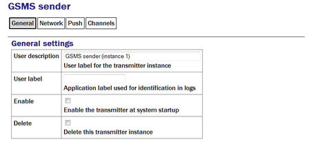
User description: Set to a meaningful name for the data that it will serve by populating the text field.
User Label: Can be filled in with a name which will then be used to identify this instance in log files.
Enable: Causes this service to start automatically when the system is re-booted. If this check-box is cleared, the service will need to be started manually (from the “Control” → “Services” menu)
Delete: Causes the configuration for this instance to be removed from the system when the form is submitted.
12.4.1.2 Network
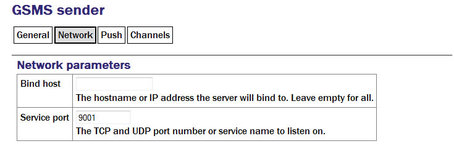
Bind host: configure the server to listen for incoming data requests only on a specific IP address. By default it will listen on all configured interfaces.
Service Port: Set the port (port number or service name) that you want the server to listen on in the text field.
12.4.1.3 Push
Push allows the server to pro-actively send data to remote GSMS receivers.
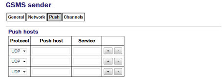
Protocol: Select TCP or UDP - this must match the receiver's setting.
Push host: Enter IP addresses (or host names).
Service: Enter port numbers (or service names)
Clicking the button on any row will open a new row. In the same way, rows can be deleted by clicking the corresponding button.
If the form is submitted when the table is full, extra blank lines are appended.
12.4.1.4 Channels
The GSMS server need not send all data from all channels to its clients. It is possible to select which channels are transmitted.
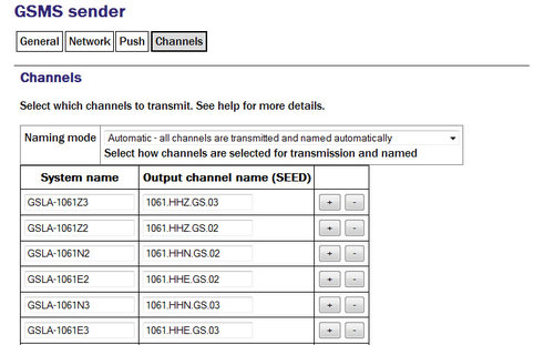
Select one of the three different naming modes:
Automatic: all channels are transmitted and named automatically
Semi-automatic: all channels are transmitted and names can be mapped using a configuration table
Manual: only channels named in the configuration table are transmitted.
The software will attempt to populate the table based on incoming data streams so it is a good idea to configure all input sources and run the system for a few minutes before completing this table.
Clicking the button on any row will open a new row. In the same way, rows can be deleted by clicking the corresponding button.
12.4.2 Configurable parameters in expert mode
The following additional configuration parameters are available by clicking the “Expert” button at the bottom of the form and selecting the 'Advanced' tab.
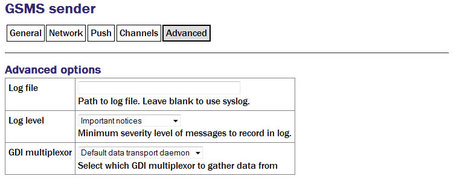
Log file: It may sometimes be desirable, for debugging purposes, to separate log messages for this transmitter from the standard system log. The text field can be populated with a path name which will then be used for dedicated logging. If left blank, logging occurs (via the standard Linux syslog facility) to /var/log/messages.
Log level: The drop-down menu controls the level of detail present in log messages, whether to syslog or to a dedicated log file. Not all of the standard syslog logging levels are available. The menu offers a choice (in order of decreasing detail) of:
Debugging information
Informational messages
Important notices
Warnings
GDI multiplexer: In most configurations, all data for all transmitters is taken from a single multiplexor, as described in section 6.1. For more complex configurations, it is possible to configure multiple multiplexers, each with their own set of input and output services. In these situations, the drop-down menu can be used to select a multiplexer instance with which to associate this transmitter. The menu offers a list of currently configured multiplexers.
12.5 Quick Seismic Characteristic Data
QSCD is a protocol developed by KIGAM (http://www.kigam.re.kr/eng) to send strong motion results, which are computed every second.
To set up a QSCD server on the acquisition module, first configure the relevant strong motion data sources as described in section 8.1.1.4, then, from the web interface, select:
Configuration → Services → Miscellaneous
or
Configuration → All options → System services → Miscellaneous
To configure a QSCD server from the command line, start gconfig and select “System services” from the top level menu.
Now select “qscd-out -- KIGAM QSCD (Quick Seismic Characteristic Data) sender ” from the System Services menu. The next screen shows a list of all QSCD server instances that have been configured:

You can reconfigure any existing service by clicking on its menu entry. To configure a new QSCD server, select “Create service instance”. The following screen allows you to configure the parameters of the server. As it is a large screen, it is shown here in pieces.
12.5.1 Configurable parameters in simple mode
The configurable parameters for the QSCD server have three tabbed pages in simple mode: General, Network and Channels.
General
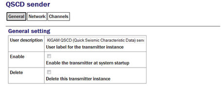
User description: Set to a meaningful name for the data that it will serve.
Enable: Causes this service to start automatically when the system is re-booted. If this check-box is cleared, the service will need to be started manually (from the “Control” → “Services” menu)
Delete: Causes the configuration for this instance to be removed from the system when the form is submitted.
Network
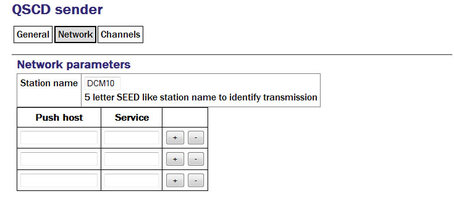
Station name: Like SEED, QSCD links require a unique name to identify the source of the data.
To send QSCD data to remote hosts, enter their DNS names or IP addresses in the table, with the associated service name or port number for each. Port names and numbers are associated with each other in the standard Linux /etc/services file.
Clicking the button on any row will open a new row. In the same way, rows can be deleted by clicking the corresponding button.
Channels
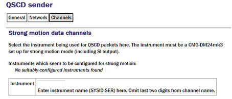
Instrument: The acquisition module scans all incoming data and prepares a list, in the correct format, of the names of instruments which are sending strong motion results. Enter one of these names in the field.
Note: The QSCD protocol only supports a single instrument. If you need to transmit results from multiple instruments, you should configure multiple QSCD sender instances, one for each instrument.
12.5.2 Configurable parameters in expert mode
The following additional configuration parameters are available by clicking the “Expert” button at the bottom of the form and selecting the 'Advanced' tab.
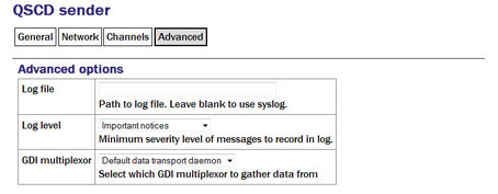
Log file: It may sometimes be desirable, for debugging purposes, to separate log messages for this transmitter from the standard system log. The text field can be populated with a path name which will then be used for dedicated logging. If left blank, logging occurs (via the standard Linux syslog facility) to /var/log/messages.
Log level: The drop-down menu controls the level of detail present in log messages, whether to syslog or to a dedicated log file. Not all of the standard syslog logging levels are available. The menu offers a choice (in order of decreasing detail) of:
Debugging information
Informational messages
Important notices
Warnings
GDI multiplexer: In most configurations, all data for all transmitters is taken from a single multiplexor, as described in section 6.1. For more complex configurations, it is possible to configure multiple multiplexers, each with their own set of input and output services. In these situations, the drop-down menu can be used to select a multiplexer instance with which to associate this transmitter. The menu offers a list of currently configured multiplexers.
12.6 WIN Sender
WIN is a Japanese seismic data format.
To set up a WIN server on the acquisition module using the web interface select:
Configuration → Services → Miscellaneous
or
Configuration → All options → System services → Miscellaneous
To configure a WIN server from the command line, start gconfig and select “System services” from the top level menu.
Now select “win-out - WIN sender ”. The screen shows a list of all WIN server instances that have been configured:
You can reconfigure any existing service by clicking on its menu entry. To configure a new WIN sender, select “Create service instance”. The following screen allows you to configure the parameters of the sender. It is shown here in parts.
12.6.1 Configurable parameters in simple mode
The configurable parameters for the WIN sender have three tabbed pages in simple mode: General, Network and Channels.
General
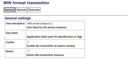
User description: Set to a meaningful name for the data that it will send.
User label: Can be set to distinguish this instance from others in the log files.
Enable: Causes this service to start automatically when the system is re-booted. If this check-box is cleared, the service will need to be started manually (from the “Control” → “Services” menu)
Delete: Causes the configuration for this instance to be removed from the system when the form is submitted.
Network
The WIN transmitter can be configured to be either a TCP server to multiple clients, or a UDP sender to a single address. If you want to sent the data to multiple clients, set up the acquisition module as a TCP server and the remote machines as clients that connect to it.
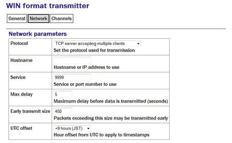
Protocol: To configure the sender as a TCP server, select “TCP server accepting multiple clients” from the drop-down list.
Hostname: To use a specific IP address to listen for requests from clients, set this in the box. By default it will listen on all interfaces.
Service: Set to the port that you want the server to listen on in the box.
If you only want to send the data to a single UDP server, select “UDP datagrams sent to specified address” from the Protocol drop-down list. Configure the remote machine's hostname or IP address in the Hostname box and set the port number that the remote machine will listen on in the Service box.
Max delay: The WIN sender will buffer up data before it is sent so that outgoing packets have a second's worth of data from all channels. If no data are received from some channels within a certain time limit, the data from other channels will be transmitted anyway. This limit is specified by the value in the field and defaults to five seconds.
Early transmit size: If a packet in construction exceeds the size specified the packet will also be sent early.
UTC Offset: The WIN Format uses the local time in order to time-stamp packets. The offset of the local time-zone from UTC used in the GCF data is specified in the box.
Channels
Note: Previous versions of the firmware required this mapping to be entered in SEED notation but this is no longer the case.
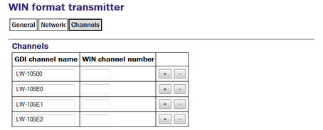
Clicking the button on any row will open a new row. In the same way, rows can be deleted by clicking the corresponding button.
12.6.2 Configurable parameters in expert mode
The following additional configuration parameters are available by clicking the “Expert” button at the bottom of the form and selecting the 'Advanced' tab.
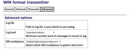
Log file: It may sometimes be desirable, for debugging purposes, to separate log messages for this transmitter from the standard system log. The text field can be populated with a path name which will then be used for dedicated logging. If left blank, logging occurs (via the standard Linux syslog facility) to /var/log/messages.
Log level: The drop-down menu controls the level of detail present in log messages, whether to syslog or to a dedicated log file. Not all of the standard syslog logging levels are available. The menu offers a choice (in order of decreasing detail) of:
Debugging information
Informational messages
Important notices
Warnings
GDI multiplexer: In most configurations, all data for all transmitters is taken from a single multiplexor, as described in section 6.1. For more complex configurations, it is possible to configure multiple multiplexers, each with their own set of input and output services. In these situations, the drop-down menu can be used to select a multiplexer instance with which to associate this transmitter. The menu offers a list of currently configured multiplexers.