Chapter 7. Networking Configuration
Platinum firmware includes comprehensive support for Ethernet networking. Features include VLAN (virtual network) support, a PPP implementation (IP over serial lines), an iptables firewall and IPV6 support.
Minimal network configuration is described in section 3.2. Those steps will allow you to communicate with your device over a network. The configuration changes made in that way will not, however, survive a reboot. To make the configuration permanent, follow the procedures in this section.
7.1 Configuring physical network interfaces
Most acquisition modules have a single physical network interface. CMG-NAMs are typically equipped with multiple physical network interfaces. Platinum firmware follows the standard Linux convention of naming the first physical network interface present on a system eth0 and subsequent interfaces eth1, eth2, etc.
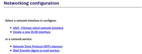
To configure a physical network interface from the web interface, select:
Configuration → Networking → Interfaces
or
Configuration → All options → Networking
The following screen will be displayed:
To configure a physical network interface from the command line, start gconfig and select “Networking” from the top level menu.
The first link on the screen takes you to the configuration page for the first physical network interface. If your hardware has multiple physical interfaces, you may need to create configurations for them using the “Create a new interface” button. Once created, the can be configured in an identical manner to eth0, as described below.
7.1.1 Configurable parameters in simple mode
The configurable parameters for physical network interface have two tabs in simple mode: Interface and Static IP.
7.1.1.1 Interface
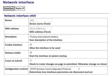
Device: Not editable. It displays the name of the network interface being configured.
MAC address: Not editable. It shows the Media Access Control address of the adapter's hardware. It is often useful to know this when configuring DHCP servers: by binding an IP address to a particular MAC address, the DHCP administrator can ensure that the device retains the same IP address across reboots.
Description: Allows the operator to modify the description of this interface in configuration dialogues and error messages. This is of limited value when there is only a single interface but, for example, when a CMG-NAM has multiple interfaces, it may be useful to rename them in order to reflect their logical function rather than their physical position.
Enable interface: Enables the interface when checked. No other configuration settings are changed when the interface is disabled, allowing use of the interface to be suspended without deleting the configuration.
Startup enable: Controls whether the interface is enabled automatically when the unit boots.
Enact on submit: Controls whether changes made using the rest of this form take effect immediately or are only written to the configuration files. When this box is cleared, changes will only take effect the next time the unit is booted or the interface is reconfigured with this box ticked.
Configuration method: The drop-down menu offers the following choices:
Static: The interface will take its address and routing parameters from values entered by the operator.
DHCP (Dynamic Host Configuration Protocol): The interface will attempt to obtain its address and routing parameters from a DHCP server.
Unconfigured but powered up (possible VLAN trunk): The interface will not be used directly but is available for carrying virtual network (VLAN) traffic.
Powered off: The interface will not be used and the interface chip is disabled, reducing the total power consumption by around 200mW.
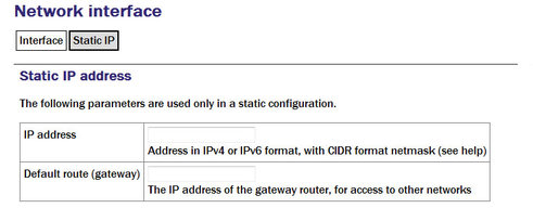
7.1.1.2 Static IP
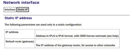
IP address: Only used if the Configuration method drop-down menu is set to “Static”. The address should be entered in CIDR format, where the address is followed by a slash and then the number of bits defining the netmask, e.g. 192.168.0.1/24 for IPV4 or 2001:db8:/32 for IPV6.
For more information about CIDR, please refer to: http://en.wikipedia.org/wiki/Classless_Inter-Domain_Routing.
Default route (gateway): Should be populated with the IP address of the default router. If more complicated routing configurations are required, these can be entered in expert mode.
7.1.2 Configurable parameters in expert mode
When in expert mode new fields are available on the “Interface” and “Static IP” tabs and there are three new tabs: DCHP options, IP aliasing and Routes.
7.1.2.1 Interface (Expert)
Media type/speed: This drop-down menu offers the following options for controlling the communication speed and duplex mode of the network link:
Automatically detected and set
Restrict speed to 10Mbps. Recommended to save power
Fixed 100baseTx, full duplex
Fixed 100baseTx, half duplex
Fixed 10baseTx, full duplex
Fixed 10baseTx, half duplex
MTU: Allows the Maximum Transfer Unit to be set for the network link. This parameter controls the maximum packet size used for outgoing network packets. If any segment of a link between two systems has a restriction on packet size, larger packets flowing across the link must be fragmented - broken into smaller parts - and then re-assembled on arrival. This is inefficient and can badly affect the throughput of a link. In such situations, it makes sense to restrict the maximum packet size at the sender (to match the limitation) so that all packets can pass unimpeded.
There is no method to empirically determine the optimum MTU for a given link from the acquisition module itself but, if the link is to a PC (or, in the case of, say, a link between two acquisition modules, one end can temporarily be replaced by a PC) the PC can be used to investigate the link properties and the correct value can be obtained.
For more information, please see http://www.dslreports.com/faq/695. Note that, if testing from a PC running Windows, the MTU of the Windows PC should be set to 1500 before starting the test.
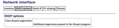
7.1.2.2 DCHP options
Extra dhcpcd arguments: Used to change the operation of the DHCP client. Please see http://man-wiki.net/index.php/8:dhcpcd for information about what options can be added here.
7.1.2.3 Static IP (Expert)
Extra ip addr arguments: Used to tune the operation of the network interface. A non-standard broadcast address can be specified by entering broadcast broadcast_address. For other settings that can be used here, please see http://linux.die.net/man/8/ip.
Nameserver: Used to specify the IP address of the DNS server for your network. This field must be set correctly before internet firmware upgrades can be used. A secondary DNS server's address can be added in the Backup nameserver field.
Default route (gateway): Populate with the IP address of the gateway router, for access to other networks or to the Internet. This field must be set correctly before internet firmware upgrades can be used.
IP route arguments: Used to modify the invocation of the ip route add command in order to, e.g., set the route metric. The options that can be set here are mostly highly technical and should rarely be required. Please see http://linux.die.net/man/8/ip for more information.
7.1.2.4 IP aliasing
IP aliasing is used to add extra addresses to this interface, a technique known as multi-homing. By default, the table displays three blank rows but, should you need more, complete the first three and submit the form: it will be re-drawn with extra blank rows. Alternatively, clicking the  button on any row will open a new row. In the same way, rows can be deleted by clicking the corresponding
  button.
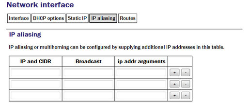
IP and CIDR: The address should be entered in CIDR format, where the address is followed by a slash and then the number of bits defining the netmask, e.g. 192.168.0.1/24 for IPV4 or 2001:db8:/32 for IPV6.
Broadcast: Enter the broadcast address to be associated with this address on the interface.
IP addr arguments: This field can be used to tune the operation of the network interface. For settings that can be used here, please see http://linux.die.net/man/8/ip.
7.1.2.5 Routes
Routes are used to add extra network and host routes to allow access to networks other than those connected via the default router specified earlier, or to force packets to traverse a particular route despite the default router setting. By default, the table displays three blank rows but, should you need more, complete the first three and submit the form: it will be redrawn with extra blank rows. Alternatively, clicking the button on any row will open a new row. In the same way, rows can be deleted by clicking the corresponding button.
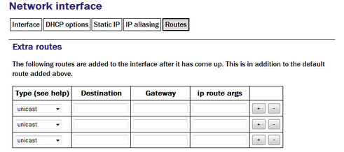
Type: This drop-down menu offers the following choices:
unicast - This is the normal setting for a host or network route. The route entry describes real paths to the destinations specified in the Destination column.
unreachable - these destinations are unreachable. Packets are discarded and the ICMP message host unreachable is generated. An EHOSTUNREACH error may appear in /var/log/messages.
blackhole - these destinations are unreachable. Packets are discarded silently. An EINVAL error may appear in /var/log/messages.
prohibit - these destinations are unreachable. Packets are discarded and the ICMP message communication administratively prohibited is generated. An EACCES error may appear in /var/log/messages.
local - the destinations are assigned to this host. The packets are looped back and delivered locally.
broadcast - the destinations are broadcast addresses. The packets are sent as link broadcasts.
Destination: The host or network to which this route offers access should be entered here in CIDR format, where the address is followed by a slash and then the number of bits defining the netmask, e.g. 192.168.0.1/24 for IPV4 or 2001:db8:/32 for IPV6.
Gateway: The IP address of the host which serves as the gateway to the specified destination.
IP route args: Used to modify the invocation of the associated ip route add command in order to, e.g., set the route metric. The options that can be set here are mostly highly technical and should rarely be required. Please see http://linux.die.net/man/8/ip for more information.
7.2 Wireless Networking
CMG-EAM and CMG-DAS units equipped with wireless networking hardware can function as clients for Wireless Access Points or participate in ad-hoc wireless networks.
To configure a wireless network interface from the web interface, select:
Configuration → Networking → Interfaces
or
Configuration → All options → Networking
The following screen will be displayed:
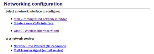
Now select 'wlan0 – Wireless interface wlan0':
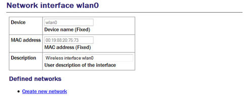
You can change the description of the wireless network if you wish.
To configure a wireless network interface from the command line, start gconfig and select “Networking” from the top level menu:
Existing defined networks can be reconfigured by clicking on the link and new networks can be defined by clicking on the “Create new network” link.
7.2.1 Configurable parameters in simple mode
The configurable parameters for wireless networking have three tabs in simple mode: Network, Access Point and IP Address.
7.2.1.1 Network
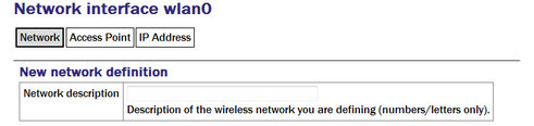
Network description: Enter a descriptive name of the network.
7.2.1.2 Access Point
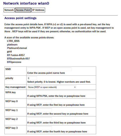
SSID: Specifies the Service Set Identifier (network name) for the desired wireless network.
Priority: Used to decide which network is chosen for connection when several configured networks are detected: connections to networks with higher priority numbers are attempted first.
Key management: Drop-down menu used to select which authentication strategy is used for this network. If WPA-PSK (WiFi Protected Access, pre-shared keys) is chosen, the following fields allow the operator to specify one or more access keys (passphrases).
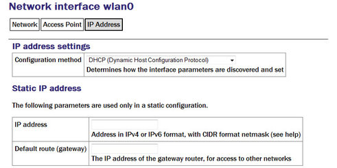
7.2.1.3 IP address
The IP address screen allows the selection of DHCP (Dynamic Host Configuration Protocol) or static addressing. If DHCP is chosen, a DHCP server will provide the unit with an IP address as well as the IP address of a default router (gateway) and, optionally, other parameters such as the address of a DNS server (name-server).
If static addressing is selected, the desired IP address and default router must be specified in the following two fields.
7.2.2 Configurable parameters in expert mode
When in expert mode new fields are available on the network and IP address forms and there are two new tabs: IP aliasing and Routes.
7.2.2.1 Network
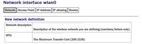
MTU: This field allows you to define a Maximum Transmission Unit (the size of the largest packet that a network protocol can transmit) for the associated network. A value which is too small will cause inefficient packetisation whereas one which is too large will cause packet fragmentation and possible disruption to communication. See the discussion in section 7.1.2 for more information.
7.2.2.2 IP Address
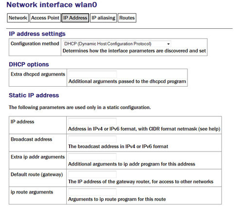
Extra dhcpcd options: Used to change the operation of the DHCP client. Please see http://man-wiki.net/index.php/8:dhcpcd for information about what options can be added here.
Extra IP addr arguments: Used to tune the operation of the network interface. A non-standard broadcast address can be specified by entering broadcast broadcast_address. For other settings that can be used here, please see http://linux.die.net/man/8/ip.
IP route arguments: Used to modify the invocation of the ip route add command in order to, e.g., set the route metric. The options that can be set here are mostly highly technical and should rarely be required. Please see http://linux.die.net/man/8/ip for more information.
7.2.2.3 IP aliasing
The IP aliasing table is used to add extra addresses to this interface, a practice known as multi-homing. By default, the table displays three blank rows but, should you need more, complete the first three and submit the form: it will be redrawn with extra blank rows. Alternatively, clicking the button on any row will open a new row. In the same way, rows can be deleted by clicking the corresponding button.
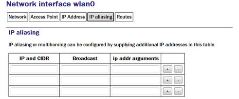
IP and CIDR: The address should be entered in CIDR format, where the address is followed by a slash and then the number of bits defining the netmask, e.g. 192.168.0.1/24 for IPV4 or 2001:db8:/32 for IPV6.
Broadcast: Enter the broadcast address to be associated with this address on the interface.
IP addr arguments: This field can be used to tune the operation of the network interface. For settings that can be used here, please see http://linux.die.net/man/8/ip.
7.2.2.4 Extra routes
Routes are used to add extra network and host routes to allow access to networks other than those connected via the default router specified earlier, or to force packets to traverse a particular route despite the default router setting. By default, the table displays three blank rows but, should you need more, complete the first three and submit the form: it will be redrawn with extra blank rows. Alternatively, clicking the button on any row will open a new row. In the same way, rows can be deleted by clicking the corresponding button.
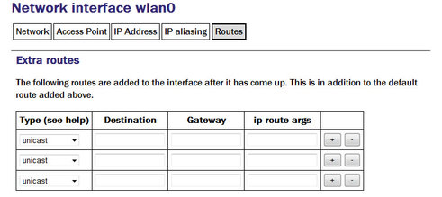
Type: The drop-down menu offers the following choices:
unicast: Normal setting for a host or network route. The route entry describes real paths to the destinations specified in the Destination column.
Unreachable: Destinations are unreachable. Packets are discarded and the ICMP message host unreachable is generated. An EHOSTUNREACH error may appear in /var/log/messages.
Blackhole: Destinations are unreachable. Packets are discarded silently. An EINVAL error may appear in /var/log/messages.
Prohibit: Destinations are unreachable. Packets are discarded and the ICMP message communication administratively prohibited is generated. An EACCES error may appear in /var/log/messages.
Local: Destinations are assigned to this host. The packets are looped back and delivered locally.
Broadcast: The broadcast addresses. The packets are sent as link broadcasts.
Destination: The host or network to which this route offers access should be entered here in CIDR format, where the address is followed by a slash and then the number of bits defining the netmask, e.g. 192.168.0.1/24 for IPV4 or 2001:db8:/32 for IPV6.
Gateway: Enter the IP address of the host which serves as the gateway to the specified destination.
ip route args: This field field can be used to modify the invocation of the associated ip route add command in order to, e.g., set the route metric. The options that can be set here are mostly highly technical and should rarely be required. Please see http://linux.die.net/man/8/ip for more information.
7.3 Virtual network (VLAN) interfaces
Platinum firmware supports the use of Virtual Local Area Networks (VLANs) to partition network traffic on the same physical subnet. Virtual interfaces can be created and assigned to a particular VLAN tag (ID) and a particular physical interface. A full discussion of VLANs is beyond the scope of this document.
To configure a virtual network interface from the web interface, select:
Configuration → Networking → Interfaces
or
Configuration → All options → Networking
The following screen is displayed:
To configure a VLAN interface from the command line, start gconfig and select “Networking” from the top level menu.
Now select 'Create a new VLAN interface'
7.3.1 Configurable parameters in simple mode
The configurable parameters for virtual network interfaces have two tabbed pages in simple mode: Interface and Static IP.
7.3.1.1 VLAN Interface
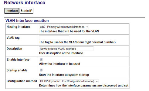
Hosting Interface drop-down menu is populated with a list of the physical interfaces present on the system. Select the physical interface over which you wish this virtual interface's traffic to flow.
VLAN tag text field should be populated with the required VLAN tag. This identifies packets sent over this interface as belonging to the specified VLAN.
Description text field can be edited to provide a more useful name for the interface.
Enable interface check-box can be ticked in order to enable the interface or cleared in order to disable it. No other configuration settings are changed when the interface is disabled, allowing use of the interface to be suspended without deleting the configuration.
Startup enable check-box controls whether the interface is enabled automatically when the unit boots.
Configuration method drop-down menu offers the following choices:
Static - The interface will take its address and routing parameters from values entered by the operator.
DHCP (Dynamic Host Configuration Protocol) - The interface will attempt to obtain its address and routing parameters from a DHCP server with a matching VLAN tag.
Powered off - The interface will not be used and the interface chip is disabled, reducing the total power consumption by around 200mW.
7.3.1.2 VLAN Static IP
If DHCP is not being used, the IP address text field should be populated with the required address in CIDR format, where the address is followed by a slash and then the number of bits defining the netmask, e.g. 192.168.0.1/24 for IPV4 or 2001:db8:/32 for IPV6.
For more information about CIDR, please refer to http://en.wikipedia.org/wiki/Classless_Inter-Domain_Routing.
The Default route (gateway) field should be populated with the IP address of the default router for this VLAN. If more complicated routing configurations are required, these can be entered in expert mode.
7.3.2 Configurable parameters in expert mode
A set of additional parameters are available when in expert mode. These are identical to the additional parameters on the physical interface configuration screen, as described in section 7.1.2 and are not discussed further here.
7.4 Network Time Protocol (NTP)
The Network Time Protocol (NTP) is a method of synchronising the clocks of computer systems over networks, including those with variable latency, such as packet-switched networks. Platinum firmware include a fully-featured NTP implementation, which can be used to keep the system clock synchronised to external time sources, such as Internet NTP servers, connected digitisers and connected GPS receivers.
Most acquisition modules include a battery-backed real-time clock (RTC) module which can retain system time with tolerable accuracy during periods of power loss. CMG-DCMs will revert to January the 1st, 1970 after each power-cycle.
The system clock is used to provide time-stamps for log-file messages and can also be used to generate NMEA and PPS signals, emulating a GPS receiver, in order to synchronise external equipment, such as a CMG-DM24 digitiser module. This technique is described in section 9.6.
The NTP subsystem displays its status in a panel of the “System status” display of the web interface. This panel includes the current system date and time, the lock status, estimated error and current clock source.
Platinum systems support two distinct timing modes, NTP and Manual. NTP is recommended for nearly all installations. Manual mode requires that the system clock be set from the command-line at least once per day and is, by its nature, considerably less accurate than NTP mode.
To configure NTP from the web interface, select:
Configuration → Data handling → Timing
or
Configuration → All options → Networking → Network Time Protocol daemon
To configure NTP from the command line, start gconfig, select “Networking” from the top level menu and then select “ Network Time Protocol (NTP) daemon”.
7.4.1 Configurable parameters
The configurable parameters for timing are presented in three tabs: General, NTP and Manual.
7.4.1.1 General tab
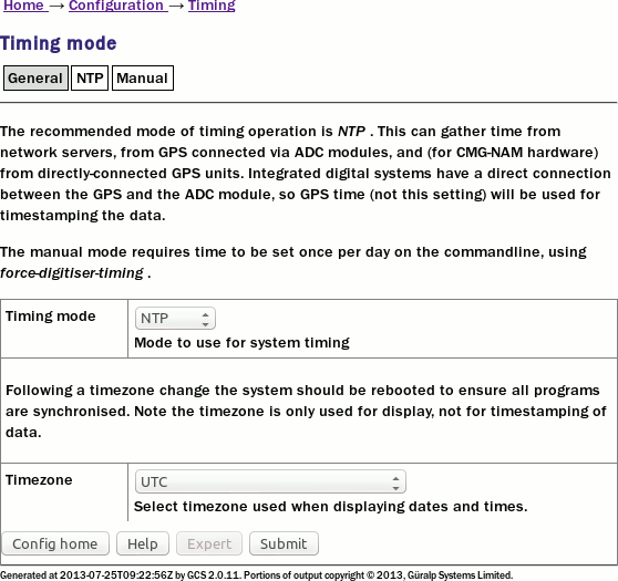
The first drop-down menu on the “General” tab, “Timing mode”, allows selection between NTP and Manual. NTP is recommended for nearly all applications.
If NTP is selected, further configuration should be carried out on the NTP tab. Likewise, if Manual is selected, further configuration should be carried out on the Manual tab.
The second drop-down menu, “Timezone”, allows selection of the time zone used when dates and times are displayed in web pages, in log-files and on the command-line. This is a system-wide setting that affects all users.
Note: Changing the time zone of the acquisition unit does not affect the timestamps of recorded data in any way. The ADC module has its own clock which always runs in UTC.
7.4.1.2 NTP tab
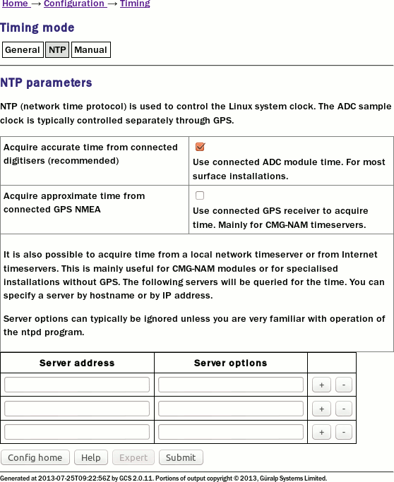
The NTP tab contains the following configurable options:
Acquire time from connected digitisers: This check-box tells the system that one or more attached digitisers are to be considered as accurate clock sources. For this to work, the digitiser must produce “RTSTATUS” packets. CMG-CD24 digitisers and digital sensors incorporating them, such as the CMG-6TD, will do this unconditionally when running firmware version 279 or later. CMG_DM24 digitisers can have these packets enabled or disabled via software (using the command RTSTATUS ENABLE). They are automatically enabled if the digitiser is ever configured via the interface in Platinum.
Acquire approximate time from connected GPS: This check-box tells the system that a GPS receiver has been attached to one of the serial ports and is to be used as a clock source. The serial port used must be configured with a “Port function” of “NMEA in. Receive GPS data for NTP” and, when used with Güralp supplied GPS receivers, must be set to 4,800 baud operation, as described in 9.6 on page 126. No further configuration is required.
Note: This setting should only be used on CMG-NAMs and CMG-NAM64s.
Server address: Allows a number of Internet or network-accessible NTP servers to be listed for use as clock sources. You can specify these servers by either IP address or hostname. If names are used, they must either be listed in the local hosts file (/etc/hosts) or resolvable via the Domain Name Service (DNS). Clicking the button on any row will open a new, blank row. In the same way, rows can be deleted by clicking the corresponding button.
7.4.2 Configurable parameters in expert mode
The only difference between standard and expert mode on this screen is the addition of a Server options column to the NTP servers table.
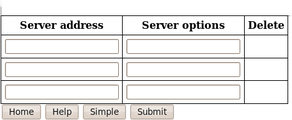
This text field can be used to provide additional control over how the NTP daemon uses the server. The options are described in the standard ntp.conf manual page, available on-line at http://linux.die.net/man/5/ntp.conf.
7.5 Email configuration
Platinum firmware is capable of sending system alerts via email over the Internet or over a local area network.
This feature is currently unused but is provided for future expansion.
To configure email from the web interface, select:
Configuration → Networking → Mail
or
Configuration → All options → Networking → Mail Transfer Agent (e-mail service)
To configure email from the command line, start gconfig, select Networking from the top level menu and then select Mail Transfer Agent (e-mail service).
7.5.1 Configurable parameters
The configurable parameters for email are contained on a single form.
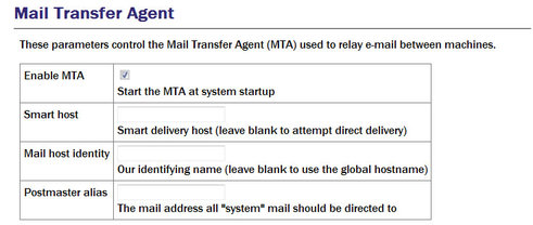
Enable MTA: Used to control whether the mail transfer agent is started automatically at boot time. If this check-box is left clear, the MTA can still be started manually from the services menu (see section 14.3.5).
Smart host: Most email configurations use a “smart host” to route mail. This can greatly simplify the administration: only one node on a network, the smart host, needs to be configured to know about any intricacies of the system and all other machines need only know the location of the smart host. If the Smart host text field is populated with the name or address of of such a host, all mail is sent directly to that host for further routing. If this field is left blank, the MTA will attempt to use DNS to discover the mail host(s) for any given address and then deliver mail directly.
Mail host identity: Specifies the hostname from which outgoing emails should appear to originate. If this field is left blank, the real hostname is used.
Postmaster alias: Specifies the address to which all internally generated mail should be sent: This should be set to the email address of the acquisition module's administrator.
7.6 Configuring the SSH Server
The acquisition module has an ssh server running on its Ethernet port which allows remote terminal access.
The ssh server, sshd, can not currently be configured using gconfig although it can be configured via the web interface. If web access is unavailable, it is possible to configure sshd from the command line by directly editing the configuration files.
7.6.1 Configuring sshd via the web interface
To configure the SSH server from the web interface, select:
Configuration → Networking → SSH server
The screen is not reproduced in this document as it is particularly large, due to the amount of explanatory text. Each option is, however, discussed below.
The version of sshd installed (openSSH) supports both version 1 and version 2 of the ssh protocol. Version 1 has some well-known weaknesses and should be avoided if at all possible, but some commercially available systems still do not support v2, so v1 is supported here for compatibility. The Enable SSH Protocol v1 check-box should be cleared unless your ssh client cannot support v2 or cannot be upgraded to support it. Click the Change server options button to commit this change.
If you want to download the ssh server's public key to allow the connecting host to check and verify the CMG-EAM's identity, use the relevant Download server public key button – there is one each for protocol versions 1 and 2. There is also the capability to command the CMG-EAM to create a new private/public key pair from this screen.
To configure password-less login to the CMG-EAM, you can upload the public key of the connecting machine to the CMG-EAM using the New client key section. Browse the connecting host's file system for the key file (usually named id_dsa.pub) and upload it here. This will allow password-less root access to the system from that machine.
Uploaded client keys are displayed in the Authorised client keys section. Any existing authorised keys can be removed: Select the check-box next to the key you wish to remove and click Remove selected keys.
Note: Password-less login via ssh v2 is, perhaps counter-intuitively, the most secure way to access your acquisition module. There is a useful discussion of the ssh protocol and full details of its usage at the site http://tinyurl.com/whyssh
Note: Systems are shipped with a pre-authorised client key to which Güralp Systems' support staff have the matching key. This allows us to access your unit and reset the root password should you forget it. You are free to delete this key if you wish.
There is a second (and significantly more complicated) way of resetting the root password if you have physical access to the system. Please contact support if you find yourself in this situation.
7.6.2 Configuring sshd from the command line
This is a complex issue and use of the web interface is strongly encouraged unless you are familiar with Linux text editors, configuration files and sshd itself. The configuration file is located at /etc/ssh/sshd_config and its syntax and semantics are described at http://man-wiki.net/index.php/5:sshd_config. More detailed discussion is beyond the scope of this document.
7.7 Working with PPP
PPP, or Point-to-Point Protocol, is a data link protocol that can carry IP packets over a serial link between two networking nodes. It can provide connection authentication, transmission encryption privacy, and compression. Platinum firmware includes an implementation of PPP which can be used to provide network links between sites or to connect to an Internet Service Provider (ISP). A number of “chat scripts” are provided, allowing connection negotiation and establishment over PSTN, GPRS and satellite modems.
7.7.1 Setting up a PPP Connection
To configure a PPP connection, you will need a user ID and authentication code (the PAP secret) as required by the remote server. In addition, a dial up (chat) script specific to the service you are using must be created. If one does not already exist for your service, please contact Güralp support.
To configure a PPP connection from the web interface, select:
Configuration → Data handling → Serial ports → Port...
or
Configuration → All options → Serial ports → Port...
To configure a PPP connection from the command line, start gconfig, select Serial ports from the top level menu and and select the port to which the modem is connected. Change the function of the port to PPP. PPP network connection, with the correct baud rate for the modem. Click  to save these changes. Go back to the configuration of the serial port and click on PPP network configuration.
7.7.2 Configurable parameters
The configurable parameters for each port on the PPP connection screen have three tabs: General, IP and Authentication.
7.7.2.1 General
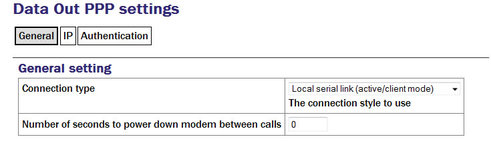
Connection type has the following options:
Local serial link (active/client mode)
Local serial link (passive/server mode)
GPRS connection via Vodafone
GPRS connection via T-Mobile
The choices available from this menu reflect the chat scripts installed on your system. If you wish to use a satellite modem or GPRS with an ISP other than those listed, please contact Güralp Systems Ltd technical support.
Number of seconds to power down modem between calls: Set the desired power-down time for the modem, if required. This can be useful with modems that are prone to entering undefined states and ensures a clean reset before each new connection.
7.7.2.2 IP
The IP addresses and routing section handles the network configuration. In active/client mode or when connecting to an ISP, the remote PPP daemon will set these parameters, in which case this section can be left blank.
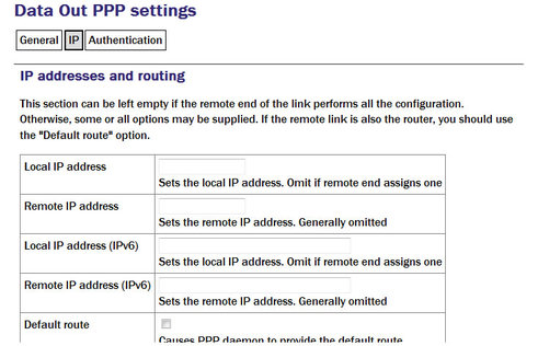
If you are using PPP between, say, two acquisition modules, one should be designated the client and the other the server. The “IP addresses and routing” parameters for the client should be left blank and those for the server completed as follows:
IPv4 networking: the Local IP address field should be populated with an IP address from an otherwise unused reserved class C network address range, such as 192.168.123.1 (with no CIDR postfix) and the Remote IP address field should be populated with an IP address from the same network, such as 192.168.123.2 - this address is provided to the client at connection initiation.
IPv6 networking: the Local IP address IPv6 and Remote IP address IPv6 fields should be populated.
Default route: If selected the PPP daemon will modify the routing table on successful connection, setting the remote end of the PPP link as the default gateway.
7.7.2.3 Authentication
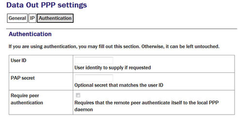
User ID / PAP secret: Use those given to you by your service provider in the appropriate fields.
The standard Linux commands ppp-on, ppp-off, ip, ping, and traceroute are available from the command line for use in controlling and testing PPP connections but it is also possible to configure a “watchdog” service to monitor a PPP connection and automatically restart it should it fail. This is described in the next section.
7.7.3 Monitoring a PPP connection
PPP connections can be monitored and, should they fail for any reason, automatically restarted.
To configure this PPP connection monitor from the web interface, select:
Configuration → Services → Network → pppd-watchdog -- PPP link watchdog
or
Configuration → All options → System services → Network → pppd-watchdog → PPP link watchdog
To configure a PPP connection monitor from the command line, start gconfig, select Services from the top level menu.
You must create a separate watchdogs for each PPP connection if you are running multiple PPP instances. This screen allows you to select any of the existing watchdog services for re-configuration or to create a new watchdog service.
7.7.4 Configurable parameters in simple mode
The configurable parameters for the PPP daemon watchdog are contained in a single form:
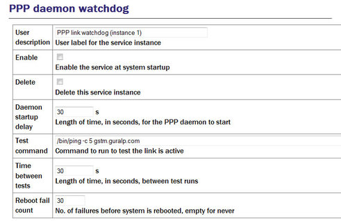
User description: If you are configuring a number of watchdogs give each of them memorable names.
Enable: Should normally be ticked but can be left clear if you only want to use the associated PPP connection occasionally.
Delete: Deletes the instance when the form is submitted.
Daemon startup delay: If the PPP connection relies on a modem link for its transport, there may be a significant delay between instructing the PPP link to start and the connection being established. So that the watchdog does not falsely detect a failed link during this period, it can be instructed to sit idle for a number of seconds before it begins to test the link. The length of the required delay should be entered into the field.
Test command: Once the start-up delay time has elapsed, the watchdog periodically tests the connection. To ensure that there is a valid end-to-end connection where, for example, a multi-hop link is in use, the exact method of testing is user-configurable: any valid command can be entered into the field and its exit status is taken to represent the link status (zero for link up, non-zero for down). The most common method used is to use the ping command to verify ICMP connectivity to the ultimate remote host, but you are free to use the command or script of your choice here, so long as it returns a non-zero exit status on link failure.
Time between tests: Determines how often the configured test is applied. It can be set high to conserve bandwidth or set low to improve failure response times. It can also be used to keep a sparsely-used link alive where a “disconnect-on-inactivity” feature would otherwise interrupt it.
Reboot fail count: If the link test fails repeatedly, the acquisition module is rebooted. Enter the number of failed tests before reboot.
The ppp watchdog service can be started, stopped and restarted using the Services page under the Control menu. See section 14.3.5.
7.7.5 Configurable parameters in expert mode
A number of additional parameters are displayed when in expert mode:
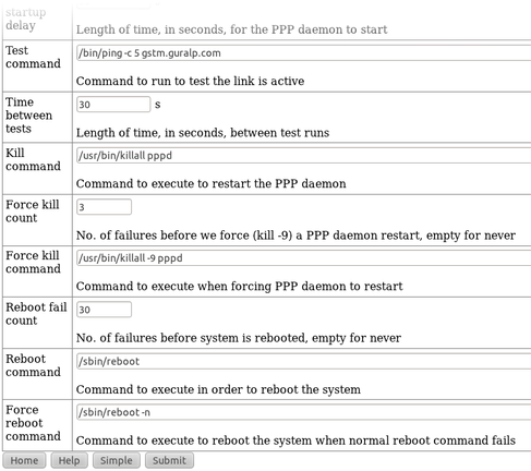
Kill command: The command which the watchdog should use to attempt to restart the PPP daemon if it is determined that the link has failed.
Force kill count: If the watchdog determines that the Kill command is not working after this number of attempts, it will try the Force kill command.
Force kill command: The command which the watchdog should use to attempt to restart the PPP daemon if it is determined that the link has failed and several attempts to restart it with the Kill command have failed to have a positive effect.
Reboot command: The command to use to reboot the system if repeated Force kills have been ineffective.
Force reboot command: The command to use to reboot the system if the normal reboot command fails to shut down the system.
7.8 Configuring TCP to serial converters
The acquisition module can act as a TCP to serial converter, effectively transporting data between one (or more) of its serial ports and a TCP connection. There are two different modes of operation, as detailed below. Any number of serial ports can be configured as TCP converters, as long as the TCP port numbers do not clash.
In “Simple server” mode, the acquisition module listens for incoming TCP connections and, should it receive one that matches its configured rules, accepts the connection and begins copying data between the serial port and the TCP connection.
The acquisition module can be configured to only listen on particular addresses and ports, to only accept connections from certain addresses or blocks of addresses and to reject connections from certain addresses or blocks of addresses.
In “Simple client mode”, the acquisition module will connect to an external TCP server on a particular address and port and then copy data bidirectionally between the serial port and the network port.
To configure the converter from the web interface, select:
Configuration → Serial Ports
then choose the required port. Set the function to “tcp serial converter”, select the baud rate, and save the settings. You can then use the TCP serial converter settings button at the bottom of the page to configure the converter.
The converter's configuration page allows you to choose the mode at the top (“Operation mode”). The other options on the page are only required in certain modes; see below for which modes require which options.
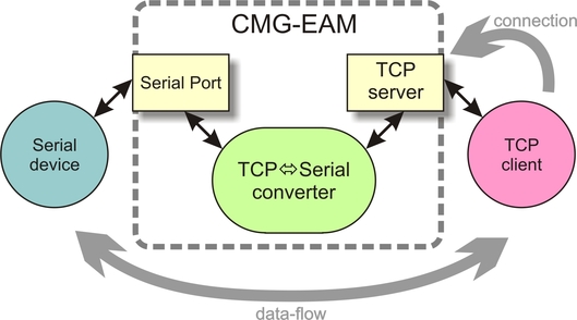
7.8.1 Simple server mode
In Simple server mode, the converter opens the serial port and creates a TCP server socket. Whenever a client connects to the socket, the converter reads raw data from the serial port and writes it to the client, and reads raw data from the client and writes it to the serial port. The serial port hardware control lines cannot be read or altered in this mode.
Simple server mode has two relevant options: the list of addresses to listen to, and an optional list of addresses to filter. The server can listen on multiple simultaneous local ports and addresses (although only one client can be active at a time).
The “Bind host” option is usually left blank. If specified, it is the name or IP address on which this server socket will listen. For example, if you specify “localhost” here, then this socket will only listen for incoming connections on the loopback address, and not on the external Ethernet port. Leave it blank to listen to all addresses.
The “Bind service” option must be specified. It is the TCP port number (1-65535) or service name (such as “tcpserial”) for the socket. This can be anything you choose, although we recommend that you use the names tcpserial, tcpserial1, tcpserial2 and so on through to tcpserial15, which are pre-defined to correspond to port numbers 10002, 10003, through to 10017.
The mapping from port names to port numbers is configured by the conventional Linux file /etc/services which can be edited from the command line if required.
If desired, you can configure a list of addresses from which to accept connections. If no addresses are configured, then all incoming addresses will be accepted. Otherwise, connections will only be accepted if they match an entry in the table with its Reject box unticked. Entries are matched in order; as soon as a match is made, the connection is accepted or rejected, and no further processing is done.
The “IP addresses” fields can each specify a host name, an IP address or an IP address range (given in CIDR format). For example, to accept connections from LAN addresses, you can add the addresses:
10.0.0.0/8
(anything from 10.0.0.0 to 10.255.255.255);172.16.0.0/12
(anything from 172.16.0.0 to 172.31.255.255);192.168.0.0/16
(anything from 192.168.0.0 to 192.168.255.255); and127.0.0.1
(loopback address).
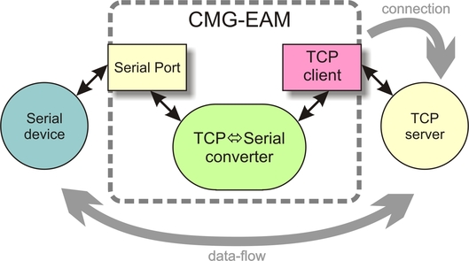
7.8.2 Simple client mode
This mode of operation is similar to simple server, except that the acquisition module establishes an outgoing TCP client connection rather than listening on a socket. It writes raw data from the serial port to the remote server, and writes raw data from the remote server to the serial port. It does not support the querying or setting of the serial port hardware control lines.
In this mode, only a single option needs to be provided: the contact details for the remote server (IP address and port). The format of this option is “host,service”. The host may be a hostname or an IP address. The service may be a TCP port number or a service name from /etc/services.