Chapter 10. Appendix 3 – Connector pin-outs
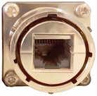
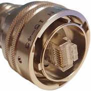
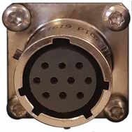
10.1 Ethernet
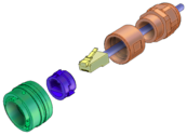
This is an Amphenol RJField-series 8P8C connector. It consists of a standard ISO 8877 8P8C modular socket (often called RJ45) in a bayonet mounting compatible with MIL‑DTL‑26482 (formerly MIL‑C‑26482). |
|
Pin | 10BASE-T & 100BASE-TX | 1000BASE-T |
1 | Transmit Data + | BI_DA+ |
2 | Transmit Data - | BI_DA- |
3 | Receive Data + | BI_DB+ |
4 | not connected | BI_DC+ |
5 | not connected | BI_DC- |
6 | Receive Data - | BI_DB- |
7 | not connected | BI_DD+ |
8 | not connected | BI_DD- |
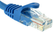
| This connector accepts unmodified ISO 8877 8P8C modular connectors (often called RJ45 connectors or Ethernet “Cat 5/6” connectors). |
|
When used in hostile environments, a standard Ethernet cable can have a mating environmental shield (Amphenol part number RJF6MN) fitted. |
10.2 Power
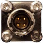
This is a standard 4-pin military-specification bayonet plug, conforming to MIL‑DTL‑26482 (formerly MIL‑C‑26482). |
|
Pin | Function |
A | Ground |
B | 10-36 V DC input |
C | not connected |
D | not connected |
| Wiring details for the compatible socket as seen from the cable end (i.e. when assembling). |
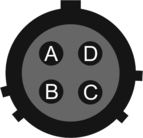
Caution: Observe the correct polarity when connecting the power supply. The red lead (from pin B) must be connected to the positive terminal, typically labelled ‘+’, and the black lead (from pin A) must be connected to the negative terminal, typically labelled ‘-’. An incorrect connection risks destroying the digitiser, the power supply and any connected instruments.
Caution: We recommend fitting an in-line 3.5 A anti-surge fuse in the positive power lead to protect the external wiring of the installation.
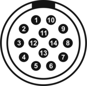
10.3 GNSS/serial
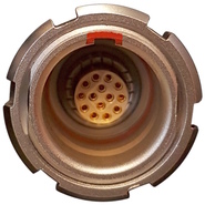
This is a 14-pin LEMO EEG.1K socket. Suitable mating connectors can be found in the LEMO FGG.1K.314 range.
|
|
Pin | Function |
1 | Ground |
2 | not connected |
3 | Ground |
4 | Debug (serial) receive |
5 | Debug (serial) transmit |
6 | not connected |
7 | GNSS power |
8 | GNSS pulse-per-second signal – RS-422 positive |
9 | GNSS receive – RS-422 positive |
10 | GNSS transmit – RS-422 positive |
11 | GNSS transmit – RS-422 negative |
12 | not connected |
13 | GNSS pulse-per-second signal – RS-422 negative |
14 | GNSS receive – RS-422 negative |
| Wiring details for the compatible plug, FGG.1K.314.*, as seen from the cable end (i.e. when assembling). |
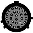
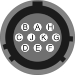
10.4 Digital
This is a standard 10-pin military-specification bayonet sockets, conforming to MIL‑DTL‑26482 (formerly MIL‑C‑26482). |
|
Pin | Function |
A | Ground |
B | Power |
C | RS422 serial transmit – positive |
D | RS422 serial transmit – negative |
E | RS422 serial receive – negative |
F | not connected |
G | not connected |
H | not connected |
I | not connected |
J | RS422 serial receive – positive |
| Wiring details for the compatible plug, ***‑12‑10P, as seen from the cable end (i.e. when assembling). |
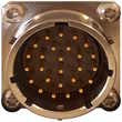
10.5 Analogue 1 and Analogue 2
These are standard 26-pin male military-specification bayonet plugs, conforming to MIL‑DTL‑26482 (formerly MIL‑C‑26482). |
|
Pin | Function | Pin | Function |
A | Vertical Acceleration/Velocity – differential non‑inverting input | P | Calibration signal (all channels) |
B | Vertical Acceleration/Velocity – differential inverting input | R | Calibration enable – vertical channel |
C | N/S Acceleration/Velocity – differential non‑inverting input | S | Calibration enable – N/S channel |
D | N/S Acceleration/Velocity – differential inverting input | T | Calibration enable – E/W channel |
E | E/W Acceleration/Velocity – differential non‑inverting input | U | Centre |
F | E/W Acceleration/Velocity – differential inverting input | V | Aux sensor input – differential non‑inverting (or single) input |
G | Vertical mass positions | W | Unlock |
H | not connected | X | Lock |
J | N/S mass positions | Y | Logic – ground* |
K | BUSY line | Z | Sensor RS232 transmit |
L | E/W mass positions | a | Sensor RS232 receive |
M | Auxiliary sensor input – differential inverting input | b | Power – ground* |
N | Signal – ground* | c | Power – positive |
* “Power – ground” and “Logic – ground” are connected together internally and also connected to the digitizer case. | |
| Wiring details for the compatible socket, ***‑16‑26S, as seen from the cable end (i.e. when assembling). |