Chapter 14. Appendices
14.1 Setting the System Identity (Hostname)
The system identity is pre-set at the factory to contain a device-type identifier and the system's serial number, such as “EAM2010”. It should not be necessary to change this but, should you desire to, the following procedure can be used.
To set the system identity using the web interface, select “System identity (hostname)” from the “Configuration” → “All options” menu. To set the system identity from the command line, start gconfig and select “System identity (hostname)” from the top level menu.
The following screen is displayed:
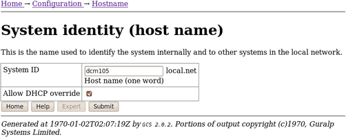
Use this screen to set the hostname of the CMG-EAM. If the Allow DHCP Override check-box is ticked then, when the system requests an IP address from a DHCP server, the server response will override the hostname set on this screen.
14.2 Authenticated Digitisers.
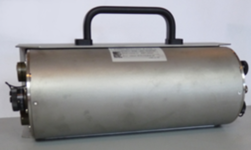
Güralp Systems Ltd's authenticated digitisers provide a CMG-DM24 and a CMG-EAM in a single package: a stainless steel or aluminium cylinder with an optional carrying/mounting bracket. An internal Spyrus PC card provides authentication and digital signing of CD1.1 frames and subframes.
The system is fitted with variable gain analogue inputs, tamper-detection lines on all key connectors and an internal USB storage device, which is available to external USB host devices such as laptop computers.
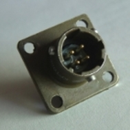
The connectors are significantly different from other packages. The analogue connectors are grouped at one end of the cylinder:
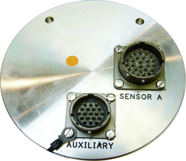
and correspond to similarly labelled connectors on a standard CMG-DM24. The illustration shows a four-channel unit; the seven-channel unit has an additional connector for sensor B.
The digital connectors are arranged at the other end of the cylinder:
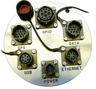
The pin-outs for each of these connectors are given in sections 14.3.6 through to 14.3.10.
14.2.1 Internal Connections
Internally, the digitiser module and acquisition module are connected using three serial lines. The exact connections depend on the synchronisation mode, determined by the service running on Port C of the acquisition module.
In all cases, the GCF data output from the digitiser module is connected to Port A of the acquisition module, which should be set to “GCF in” at 38,400 Baud. It is currently possible to set the Baud rate of the digitiser's data output port and of the EAM's Port A independently, leading to a loss of data communication between the two modules if the two do not match. If you wish to have a higher transfer rate between the two modules, both ends must have their Baud rates increased separately.
The digitiser module also exposes a dedicated console connection, which is internally attached to Port B of the acquisition module. This can be accessed from the command line of the acquisition module or, if desired, made accessible over the network. If you wish to disallow network access, set the service on the EAM's Port B to “none”. To enable access over the network, set the service on the EAM's Port B to “TCP serial converter. Serial data to TCP link converter” and configure the converter according to the instructions in section 6.7.
It is currently possible to set the Baud rate of the digitiser's console port and of the EAM's Port B independently, leading to a loss of data communication between the two modules if the two do not match. If you wish to have a higher transfer rate between the two modules, both ends must have their Baud rates increased separately. The digitiser module's Baud rate must be changed first.
Port C of the acquisition module is used for synchronisation and can either provide NMEA to the digitiser module or share incoming GPS data from an external receiver. Different internal connections are used in each case: an analogue switch is controlled by the service selected for the EAM's Port C.
When the Port C service is set to “NMEA In”, the connections are as follows:
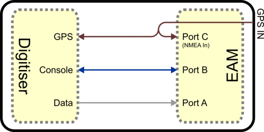
Incoming data from an external GPS receiver is available to both the digitiser and acquisition modules. Both the digitiser's GPS input and Port C of the acquisition module must run at 4,800 Baud. This should never be changed.
If an external GPS receiver is used but it is not required to use its data in the EAM, the service on Port C can be set to “none”.
If use of a GPS receiver is impractical but internet-derived NTP synchronisation is available, this can be used as the clock source for both the digitiser module and the acquisition module. By setting the service on Port C to “NMEA out”, the following connections are enabled:
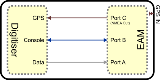
Both the digitiser's GPS input and Port C of the acquisition module must run at 4,800 Baud. This should never be changed. Note that, in this mode, the external GPS socket is disconnected: it cannot be used as an output for additional digitisers.
14.2.2 Variable Gain Inputs
The authenticated digitiser is fitted with a programmable gain differential input amplifier which can be set to ×1, ×2, ×4, ×8, ×16, ×32 or ×64 gain operation.
The gain can be set individually for each input channel, either using the Platinum web configuration interface or directly from the digitiser's command line. In either case, the digitiser module must be re-booted before the new value will take effect.
The gain settings are reported in the status stream at boot time:
ADC #1 Version 760303
ADC o/s nulls 0 0 0 0
4 channel system
Gain Control : E8
Gain settings : Ch#0 *1 Ch#1 *1 Ch#2 *1 Ch#3 *1
In the example above, all channels are set to unity gain (channel 0 is the vertical component and 1, 2 and 3 are the North/South, East/West and auxiliary/calibration channels, respectively. On a seven-channel digitiser, channels 4, 5 and 6 are the vertical, North/South and East/West components for the second instrument). If variable-gain-aware firmware (v106b42 and above) is loaded on a digitiser without variable-gain hardware, the text “No gain stage” will appear in this position in the boot status stream.
The selected gain setting is encoded into the GCF headers by appropriating bits from the System ID which must, therefore, be chosen to be five (or fewer) characters long. See the note at the end of this section for more information. The InfoBlocks (see section 7 on page78) should be changed to reflect the amended System ID but the gain figure taken from the calibration document should be used unchanged, regardless of the variable gain setting chosen. Similarly the “calvals” file in Scream! should not be changed, other than to reflect the System ID; Scream! can deduce the variable gain settings in use from the GCF block headers and automatically take account of these during calibration operations.
To change the gain using the web interface, select the digitiser from the list in the “System setup” section of the “Configuration” menu and scroll down to the “Connected devices” section. The following additional sub-section appears:
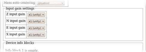
(This table is extended to show three additional components when a seven-channel digitiser is detected.)
From here, the gain can be set individually for each component. If the “Submit” button is clicked, the changes will be stored in the digitiser module's configuration but will not take effect until the module is rebooted. If an immediate change is required, the “Submit & Reboot digitiser” button should be used instead.
To change the gain using the command line, use the data-terminal command to connect to the digitiser, as described in section 13.2.2.2 on page 177 and issue one of the following two commands.
To simultaneously set all channels to the same gain, enter the command:
gain *gains
where gain is one of 1, 2, 4, 8, 16, 32 or 64. For example, to select ×8 gain on all channels, enter the command
8 *gains
The digitiser must be rebooted before the change will take effect.
To set the gain for an individual channel, enter the command:
channel gain *gain
where channel is one of 0 (vertical), 1 (North/South), 2 (East/West) or 3 (auxiliary/calibration). On seven channel digitisers, this parameter can also be one of 4 (vertical), 5 (North/South) or 6 (East/West), referring to the components from the second instrument. gain is one of 1, 2, 4, 8, 16, 32 or 64. For example, to select ×16 gain on just the vertical channel, enter the command
0 16 *gains
The digitiser must be rebooted before the change will take effect.
Note: Software developers working with GCF packets can decode the selected gain setting from the GCF header as follows:
If the most significant bit of the System ID is zero, variable gain is not used. If the most significant two bits of the System ID are 10 or 11, the next three bits encode the gain, using this code:
Bits 2, 3 & 4 | Gain |
000 | not fitted |
001 | ×1 |
010 | ×2 |
011 | ×4 |
100 | ×8 |
101 | ×16 |
110 | ×32 |
111 | ×64 |
14.2.3 USB operations
The Authenticated Digitiser can behave as a USB storage device (via the GPIO connector) or as a USB host (via the USB connector).
14.2.3.1 USB device mode
The Authenticated Digitiser is fitted with an internal Flash memory device which is accessible via USB. It can be written to by selecting “Internal USB storage” from the “Recording destination” drop-down menu on the “Disk recording” menu (see section 10.2 on page 109).
When a USB host, such as a laptop or PC, is connected to the GPIO port (who's pin-out is given in section 14.3.6) internal circuitry detects the USB power and automatically connects the Flash memory to the USB socket, causing it to behave identically to a standard USB memory stick.
When no power is detected at the USB port, the Flash memory is available to the system as if it were a standard removable disk. All of the disk recording options described in section 10.2 (on page 109) will apply to this device.
14.2.3.2 USB host mode
If a USB storage device is connected to the USB port (who's pin-out is given in section 14.3.8), it will be mounted under /media. It can be used to store seismic data by selecting “External USB drive on mil-spec connector” from the “Recording destination” drop-down menu on the “Disk recording” menu (see section 10.2 on page 109).109
14.3 Connector pin-outs
14.3.1 Peli-case: PORTs A, B, C....
These are standard 10-pin “mil-spec” sockets, conforming to MIL-DTL-26482 (formerly MIL-C-26482). A typical part-number is 02E-12-10S although the initial “02E” varies with manufacturer. Suitable mating connectors have part-numbers like ***-12-10P and are available from Amphenol, ITT Cannon and other manufacturers. |
|
The pin-out is such that the port can be connected to the serial output of a DM24 digitizer using a straight-through cable.
Pin | Function |
A | Power 0 V |
B | Power +10 to +35 V |
C | RS232 RTS |
D | RS232 CTS |
E | RS232 DTR |
F | RS232 DSR |
G | RS232 ground |
H | RS232 CD |
J | RS232 transmit |
K | RS232 receive |
| Wiring details for the compatible plug, ***-12-10P, as seen from the cable end (i.e. during assembly). |
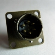
14.3.2 Peli-case: DATA OUT port
This is a standard 10-pin “mil-spec” plug, conforming to MIL-DTL-26482 (formerly MIL-C-26482). A typical part-number is 02E-12-10P although the initial “02E” varies with manufacturer. Suitable mating connectors have part-numbers like ***-12-10S and are available from Amphenol, ITT Cannon and other manufacturers. |
|
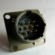
The pin-out is the same as the serial output of a DM24 digitizer, allowing you to insert a CMG-EAM into a pre-existing installation and maintain connectivity.
Pin | Function |
A | Power input, 0 V |
B | Power input, +10 to +35 V |
C | RS232 CTS |
D | RS232 RTS |
E | RS232 DTR |
F | RS232 DSR |
G | RS232 ground |
H | RS232 CD |
J | RS232 receive |
K | RS232 transmit |
| Wiring details for the compatible socket, ***-12-10S, as seen from the cable end (i.e. during assembly). |

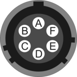
14.3.3 Peli-case: USB
This is a standard 6-pin “mil-spec” socket, conforming to MIL-DTL-26482 (formerly MIL-C-26482). A typical part-number is 02E-10-06S although the initial “02E” varies with manufacturer. Suitable mating connectors have part-numbers like ***-10-06P and are available from Amphenol, ITT Cannon and other manufacturers. |
|
Pin | Function |
A | +5 V DC (USB Type A pin 1) |
B | Data –ve (USB Type A pin 2) |
C | Data +ve (USB Type A pin 3) |
D | 0 V (USB Type A pin 4) |
E | Shielding |
F | Switched power +10 to +35 V |
| Wiring details for the compatible plug, ***-10-06P, as seen from the cable end (i.e. during assembly). |
14.3.4 Peli-case: NETWORK
This is a standard 6-pin “mil-spec” plug, conforming to MIL-DTL-26482 (formerly MIL-C-26482). A typical part-number is 02E-10-06P although the initial “02E” varies with manufacturer. Suitable mating connectors have part-numbers like ***-10-06S and are available from Amphenol, ITT Cannon and other manufacturers. |
|
Pin | Function |
B | Data transmit +ve (RJ45 pin 1) |
C | Data receive +ve (RJ45 pin 3) |
E | Data receive –ve (RJ45 pin 6) |
F | Data transmit –ve (RJ45 pin 2) |
| Wiring details for the compatible socket, ***-10-06S, as seen from the cable end (i.e. during assembly). |

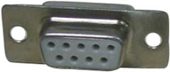
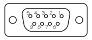
14.3.5 Peli-case: Console
This is a standard DE9F (TIA-574) sub-miniature (D-sub) line socket, conforming to DIN 41652 and MIL-DTL-24308. They are very widely available, as are suitable mating connectors. |
|
Pin | Function |
1 | not connected |
2 | RS232 transmitted data |
3 | RS232 received data |
4 | not connected |
5 | Ground |
6 | not connected |
7 | not connected |
8 | not connected |
9 | not connected |
| Wiring details for the compatible plug, DE9M, as seen from the cable end (i.e. during assembly). |
14.3.6 Cylinder: GPIO
These are standard 12-pin “mil-spec” sockets, conforming to MIL-DTL-26482 (formerly MIL-C-26482). A typical part-number is 02E-14-12S although the initial “02E” varies with manufacturer. Suitable mating connectors have part-numbers like ***-14-12P and are available from Amphenol, ITT Cannon and other manufacturers. |
|
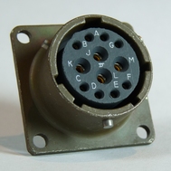
The USB lines provide external host access to the internal USB memory device. When power is sensed on pin J, an internal switch disconnects the memory device from the internal circuitry and connects it to this socket.
Pin | Function |
A | USB Data -ve (USB Type A pin 1) - see text above. |
B | USB Data +ve (USB Type A pin 3) - see text above. |
C | Anti-tamper line 4 |
D | Anti-tamper line 3 |
E | Anti-tamper line 2 |
F | Anti-tamper line 1 |
G | Console transmit (RS232 TXD) |
H | Console receive (RS232 RXD) |
J | USB Power input (USB Type A pin 1) - see text above. |
K | Ground (USB Type A pin 4) |
L | Anti-tamper line 0 |
M | Ground |
| Wiring details for the compatible plug, ***-14-12P, as seen from the cable end (i.e. during assembly). |
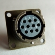
14.3.7 Cylinder: GPS
This is a standard 10-pin “mil-spec” plug, conforming to MIL-DTL-26482 (formerly MIL-C-26482). A typical part-number is 02E-12-10P although the initial “02E” varies with manufacturer. Suitable mating connectors have part-numbers like ***-12-10S and are available from Amphenol, ITT Cannon and other manufacturers. |
|
The pin-out is the same as the GPS input of a DM24 digitizer.
Pin | Function |
A | Power 0 V |
B | Power +12 V |
C | 1pps signal |
D | not connected |
E | Digitizer console transmit |
F | Digitizer console receive |
G | RS232 ground |
H | Digitizer console ground |
J | RS232 transmit to GPS |
K | RS232 receive from GPS |
| Wiring details for the compatible socket, ***-12-10S, as seen from the cable end (i.e. during assembly). |
14.3.8 Cylinder: USB
This is a standard 6-pin “mil-spec” socket, conforming to MIL-DTL-26482 (formerly MIL-C-26482). A typical part-number is 02E-10-06S although the initial “02E” varies with manufacturer. Suitable mating connectors have part-numbers like ***-10-06P and are available from Amphenol, ITT Cannon and other manufacturers. |
|
Pin | Function |
A | +5 V DC (USB Type A pin 1) |
B | Data –ve (USB Type A pin 2) |
C | Data +ve (USB Type A pin 3) |
D | 0 V (USB Type A pin 4) |
E | Shielding |
F | not connected |
| Wiring details for the compatible plug, ***-10-06P, as seen from the cable end (i.e. during assembly). |
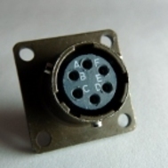
14.3.9 Cylinder: Power
This is a standard 4-pin “mil-spec” plug, conforming to MIL-DTL-26482 (formerly MIL-C-26482). A typical part-number is 02E-08-04P although the initial “02E” varies with manufacturer. Suitable mating connectors have part-numbers like ***-08-04S and are available from Amphenol, ITT Cannon and other manufacturers. |
|
Pin | Function |
A | Ground |
B | +ve supply input |
C | Anti-tamper line 5 |
D | External switched power output #1 |
| Wiring details for the compatible socket, ***-08-04S, as seen from the cable end (i.e. during assembly). |

14.3.10 Cylinder: Ethernet
This is a standard 6-pin “mil-spec” plug, conforming to MIL-DTL-26482 (formerly MIL-C-26482). A typical part-number is 02E-10-06P although the initial “02E” varies with manufacturer. Suitable mating connectors have part-numbers like ***-10-06S and are available from Amphenol, ITT Cannon and other manufacturers. |
|
Pin | Function |
A | Ground |
B | Data transmit +ve (RJ45 pin 1) |
C | Data receive +ve (RJ45 pin 3) |
D | External switched power output #0 |
E | Data receive –ve (RJ45 pin 6) |
F | Data transmit –ve (RJ45 pin 2) |
| Wiring details for the compatible socket, ***-10-06S, as seen from the cable end (i.e. during assembly). |
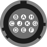
14.3.11 Cylinder: Data
This is a standard 10-pin “mil-spec” plug, conforming to MIL-DTL-26482 (formerly MIL-C-26482). A typical part-number is 02E-12-10P although the initial “02E” varies with manufacturer. Suitable mating connectors have part-numbers like ***-12-10S and are available from Amphenol, ITT Cannon and other manufacturers. |
|
Pin | Function |
A | Power input, 0 V |
B | Power input, +10 to +36 V |
C | RS232 CTS |
D | RS232 RTS |
E | External trigger output |
F | External trigger output |
G | RS232 ground |
H | External trigger input |
J | RS232 receive |
K | RS232 transmit |
| Wiring details for the compatible socket, ***-12-10S, as seen from the cable end (i.e. during assembly). |
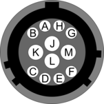
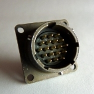
14.3.12 Cylinder: SENSOR A & B
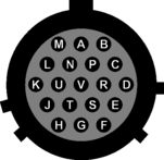
This is a standard 26-pin “mil-spec” plug, conforming to MIL-DTL-26482 (formerly MIL-C-26482). A typical part-number is 02E-16-26P although the initial “02E” varies with manufacturer. Suitable mating connectors have part-numbers like ***-16-26S and are available from Amphenol, ITT Cannon and other manufacturers. |
|
Pin | Function | Pin | Function |
A | Vertical velocity +ve | P | Calibration signal |
B | Vertical velocity –ve | R | Vertical calibration enable |
C | N/S velocity +ve | S | N/S calibration enable |
D | N/S velocity –ve | T | E/W calibration enable |
E | E/W velocity +ve | U | Centre |
F | E/W velocity –ve | V | not connected |
G | Vertical mass position | W | Unlock |
H | not connected | X | Lock |
J | N/S mass position | Y | Logic signal ground |
K | Busy indicator LED | Z | not connected |
L | E/W mass position | a | not connected |
M | not connected | b | Power 0 V |
N | Signal ground | c | Power +10 to +24 V |
| Wiring details for the compatible socket, ***-16-26S, as seen from the cable end (i.e. during assembly). |
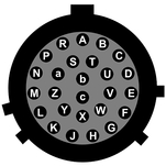
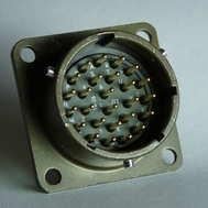
14.3.13 Cylinder: Auxiliary Input
This is a standard 19-pin “mil-spec” plug, conforming to MIL-DTL-26482 (formerly MIL-C-26482). A typical part-number is 02E-14-19P although the initial “02E” varies with manufacturer. Suitable mating connectors have part-numbers like ***-14-19S and are available from Amphenol, ITT Cannon and other manufacturers. |
|
Pin | Function | Pin | Function |
A | Optional SENSOR B auxiliary / calibration channel +ve | L | SENSOR A signal ground |
B | Optional SENSOR B auxiliary / calibration channel –ve | M | Optional SENSOR B |
C | Optional SENSOR B signal ground | N | Digital ground |
D | Optional SENSOR B Mux channel M3 | P | not connected |
E | Optional SENSOR B Mux channel M4 | R | SENSOR A Mux channel MB |
F | Optional SENSOR B Mux channel M7 | S | SENSOR A Mux channel MC |
G | not connected | T | SENSOR A Mux channel MF |
H | Optional SENSOR B Mux channel M5 | U | SENSOR A Mux channel MD |
J | SENSOR A auxiliary / calibration channel +ve | V | SENSOR A Mux channel ME |
K | SENSOR A auxiliary / calibration channel –ve |
| Wiring details for the compatible socket, ***-14-19S, as seen from the cable end (i.e. during assembly). |
14.4 Using Minicom
The CMG-EAM includes the Linux program minicom as a terminal emulator for use with serial devices, including Güralp digitisers. The following is part of the minicom man page.
Minicom is window based. To pop up a window with the function you want, hold the  key while typing
  (from now on, we will use + to denote this), and then the function key (a-z or A-Z). By pressing + first and then
  , a help screen comes up with a short summary of all commands.
For every menu the following keys can be used:
|
|
|
|
|
|
|
|
|
|
|
|
 or
or 
 or
or 
 or
or 
 or
or 


The screen is divided into two portions: the upper 24 lines are the terminal-emulator screen. In this window, ANSI or VT100 escape sequences are interpreted. If there is a line left at the bottom, a status line is placed there. If this is not possible the status line will be showed every time you press +. On terminals that have a special status line, it will be used if the termcap information is complete and the -k flag has been given. Possible commands are listed next, in alphabetical order.
| Pressing |
| Toggle 'Add Linefeed' on/off. If it is on, a linefeed is added before every carriage return displayed on the screen. |
| Gives you a scroll back buffer. You can scroll up with |
| Clears the screen. |
| Toggle local echo on and off. |
| A break signal is sent. |
| Toggle the type of escape sequence that the cursor keys send between normal and applications mode. (See also the comment about the status line below). |
| Jump to a shell. On return, the whole screen will be redrawn. |
| Clears the screen, runs kermit and redraws the screen upon return. |
| Turn Capture file on off. If turned on, all output sent to the screen will be captured in the file too. |
| Configure minicom. Puts you in the configuration menu. |
| Communication Parameters. Allows you to change the bps rate, parity and number of bits. |
| Exit minicom without resetting the modem. If macros changed and were not saved, you will have a chance to do so. |
| Receive files. Choose from various protocols (external). If you have the filename selection window and the prompt for download directory enabled, you'll get a selection window for choosing the directory for downloading. Otherwise the download directory defined in the Filenames and paths menu will be used. |
| Send files. Choose the protocol like you do with the receive command. If you don't have the filename selection window enabled (in the File transfer protocols menu), you'll just have to write the filename(s) in a dialog window. If you have the selection window enabled, a window will pop up showing the filenames in your upload directory. You can tag and untag filenames by pressing spacebar, and move the cursor up and down with the cursor keys or j/k. The selected filenames are shown highlighted. Directory names are shown [within brackets] and you can move up or down in the directory tree by pressing the spacebar twice. Finally, send the files by pressing ENTER or quit by pressing ESC. |
| Choose Terminal emulation: Ansi(color) or vt100. You can also change the backspace key here, turn the status line on or off, and define delay (in milliseconds) after each newline if you need that. |
| Toggle line-wrap on/off. |
| Exit minicom, reset modem. If macros changed and were not saved, you will have a chance to do so. |
| Paste a file. Reads a file and sends its contents just as if it would be typed in. |
| Pop up the help screen. |

 , down with
  , a page up with
  and, if you have them, the
 keys can also be used. You can search for text in the buffer with
  (case-sensitive) or
  +
+ will find the next occurrence of the string.
  will enter citation mode. A text cursor appears and you specify the start line by hitting


