Chapter 7. Digitiser Configuration
7.1 Configuring Digitisers using the web interface
The configuration interface can be used to configure the digitiser module in a CMG-DAS or any serially attached Güralp digitiser, such as CMG-DM24 or CMG-CD24. The internal digitiser module in a CMG-DAS is, effectively, serially connected so both internal and external digitisers are handled identically.
The “System Setup” sub-menu of the “Configuration” menu alters dynamically to reflect the system's embedded and attached devices. For every digitiser detected, an entry appears which allows you to configure the digitiser.
Note: To control (as opposed to configure) the digitiser and its attached instrument (sensor locking, mass centring, etc.) see section 13.2.2 on page 173.
The digitiser configuration screen is large and is shown here in sections. The first section displays the digitiser's identification string and serial number and allows these to be set. It also displays the digitiser's software version:
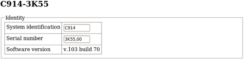
The system identification string and serial number can be changed by altering these fields and then clicking the “Submit changes” button at the bottom of the screen. If the digitiser is running in dual serial mode, both serial numbers are displayed on this screen in separate rows.
The next section configures the digitiser for its attached devices:
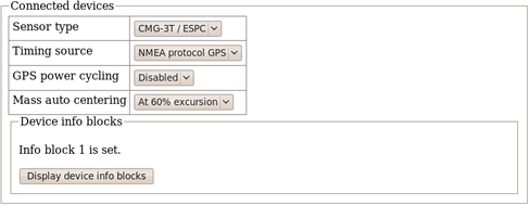
The sensor type can be set although this has no effect on the CMG-EAM's operation and acts as a memo field.
The timing source for the digitiser should be set to “NMEA protocol GPS” (which should be used for all GPS devices) or “None”, for situations where there is no timing source.
GPS units can be turned off to save power in battery-powered environments. In order to keep the internal clock synchronised, the GPS unit is regularly turned on for long enough to obtain an accurate time and then turned off. The “GPS power-cycling” drop-down allows you to select the intervals at which this happens (1, 2, 3, 4, 6, 8, 21 or 24 hours) or whether to leave the GPS constantly powered up.
“Info blocks” are areas of storage within the digitiser which can hold arbitrary data. In some applications, such as when generating strong motion packets, they should hold structured information about the attached sensors. Refer to the strong motion set-up guide for more information about this topic. If you do not need them to hold structured data, you can use them to store any information you wish, such as sensor details. There are one or two info blocks per digitiser and the display will recognise this fact. The “Display device info blocks” button shows the contents of the infoblocks and allows you to upload new data to them, should you wish.
The next section of the screen controls the latency mode and compression mode of the digitiser. Low latency mode is intended for use with strong motion calculations. The digital filtering is changed from finite impulse response (FIR) to infinite impulse response (IIR) and packets are output each second at twenty samples per second in order to achieve very near real time data.
Low latency mode cannot be selected unless certain preconditions are met: for example, the first decimator output must be set to two hundred samples per second. If all preconditions are satisfied, the Enable low latency operation button is enabled. As an alternative, the Force low latency operation button can be used to make all necessary changes before enabling low latency mode.
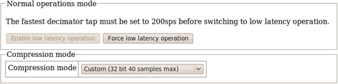
The Compression mode drop-down menu controls how samples are packed, affecting both data latency and line utilisation. GCF packets contain a 32-bit starting value and then a series of differences between consecutive samples. When the input signal is relatively quiet, these differences can often be expressed as 8-bit quantities. When the input signal includes large transients, the differences are transmitted as 32-bit quantities. For intermediate level signals, 16-bit values can be used. This is known as compression as it can “compress” four samples into the space otherwise occupied by a single value. The digitiser can be configured to limit the amount of compression used.
The difference values are stored in records, which are four bytes long and, so, may contain four 8-bit differences, two 16-bit differences or one 32-bit difference. A GCF packet can contain up to 250 records so the maximum number of samples in a packet is between 250 (when 32-bit differences are used) and 1000 (for eight-bit differences).
Packets must start on whole-second boundaries, so they are not always filled. In addition, it is possible to configure the digitiser to further restrict the number of records in a packet in order to decrease latency.
The drop-down menu controls both of these settings and usually offers the following choices:
“Recommended (8-bit 20 records max)” - this setting represents the best compromise for throughput: allowing 8-bit compression potentially increases the number of samples per packet and limiting packets to twenty records guarantees reasonably low latency.
“On (8-bit 250 records max)” - this setting optimises line utilisation, allowing maximum compression and minimising the number of packet headers transmitted.
“Off (32-bit 20 samples max)” - this setting disables compression, forcing samples to be transmitted as 32-bit differences. Latency is reduced by limiting the number of records to twenty per packet.
If the system is connected to a digitiser that is using a different combination of compression control and sample limits, it will appear as an extra item in the drop-down menu, labelled “Custom”. For example:
“Custom (16-bit 40 samples max)”
would appear if these settings had been manually configured from, say, the digitiser's command line.
The “Decimator outputs” section of the screen shows and controls which digitiser taps have been configured to output data, both in continuous and triggered states.
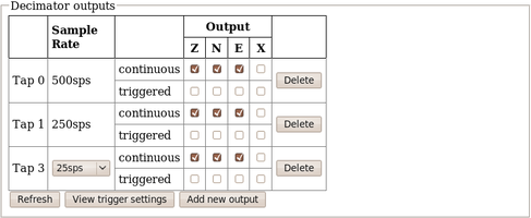
The output column is extended when using 7-channel digitisers. Extra taps can be added with the “Add new output” button. The rates available at each tap are dependant on the rate selected at the previous tap: the base sampling rate is 2000 samples per second and each tap can be configured to divide this by either 2, 4 or 5. The available rates are shown in the table below, along with a way to configure each, although there are sometimes very many different ways to configure any given rate.
Desired | Intermediate |
4 | 400, 100, 20 |
5 | 400, 100, 20 |
8 | 400, 200, 40 |
10 | 400, 100, 50 |
16 | 400, 80 |
20 | 400, 100 |
25 | 400, 100 |
40 | 400, 200 |
50 | 400, 250 |
80 | 400 |
100 | 400 |
125 | 500 |
200 | 400 |
250 | 500 |
400 | tap 1 |
500 | tap 1 |
1000 | tap 1 |
The triggering settings are normally hidden but can be revealed by clicking the “View trigger settings” button. The following extra dialogues are displayed:
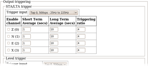
STA/LTA triggers activate when the ratio of the short-term average to the long-term average (of the input signal) exceeds a configured value. The trigger input drop-down menu allows the selection of the input signal to be used for these calculations, along with one of three filter settings. The available filters have lower corner frequencies based on fixed fractions of the sample frequency: specifically, 5%, 15% and 25% of the sample rate. The upper corner is the Nyquist frequency (half the sample rate). For example, if a tap configured for 25 samples per second, the three filters offered will have pass-bands of 1.25Hz to 11.25Hz, 2.5Hz to 11.25Hz and 6.125Hz to 11.25Hz.
The periods over which the short term and long term averages are computed, along with the triggering ratio itself, can be altered by changing values in the table. The check-boxes next to each component are used to enable or disable the use of that component's output in the STA/LTA triggering algorithm.
Level triggering is controlled by the following dialogue:
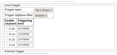
The tap to be used as input should be selected from the Trigger input drop-down menu. All configured taps are available, regardless of whether they have been selected for continuous output or not. An optional highpass filter can be applied to eliminate the effect of any DC offset in the sensor's output. The available corner frequencies are 100, 300 and 1000 seconds.
The check-boxes labelled with component designators are used to include or exclude the associated component from the triggering algorithm. If one is ticked, a trigger will be activated if that component's instantaneous output exceeds the value entered into the Triggering level field in the same row.
The final section of the triggering configuration screen concerns external triggering and pre- and post-trigger times.
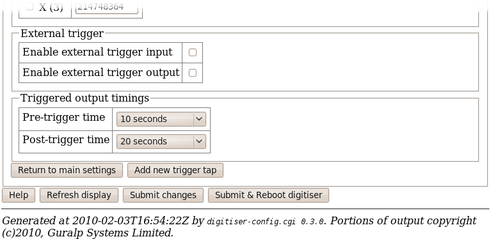
Full coverage of external triggering is beyond the scope of this manual and the interested reader is referred to the relevant digitiser manual.
The pre-trigger time and post-trigger time drop-down menus control the amount of data transmitted around each trigger period. The options offered range from 5 seconds to 4 minutes. The “0 seconds” setting disables the feature.
The “Add new trigger tap” button inserts and extra row in the decimator output table and returns the display to the main digitiser configuration settings screen.
The next section of the main display shows and controls the transmission of data from the auxiliary and state-of-health channels of the digitiser:
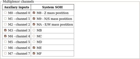
Inputs M3 through M7 and MB through MF are typically derived by digitising (at 16-bit resolution) the analogue inputs on the “Auxiliary” connector of the digitiser although, in some configurations, they may be connected to internal sensors. M8, M9 and MA provide mass position data from the first sensor and, for seven-channel digitisers, M0, M1 and M2 perform the same function for the second instrument. Output from each displayed channel can be enabled by ticking the associated check-box or disabled by clearing it.
This is followed by the Transmission Mode selection dialogue (not reproduced here). One mode can be selected from the following list:
Direct mode - Data are transmitted in real-time, without being copied to local storage. Only a small transmit buffer is used.
Filing mode - Data are stored in local flash storage. A periodic status heartbeat is transmitted to inform listeners that data are available from storage.
Adaptive mode - Data are transmitted in real-time whenever possible. Any unacknowledged transmission is stored, and retransmitted oldest first when the line is not being used for real-time traffic.
FIFO mode - Data are stored locally and transmitted in strict FIFO order. If the link is lost for a period, real-time data will be delayed while the stored data are transmitted.
Dual mode - Continuous data are transmitted as in "direct" mode and Triggered data is stored in flash as in "filing" mode.
Duplicate mode - Data are transmitted as if in "direct" mode and also stored in flash as in "filing" mode although without the "heartbeat" operation.
The next section of the web page allows the selection of one of two storage modes, which affect how data are stored in the digitiser's local flash storage:
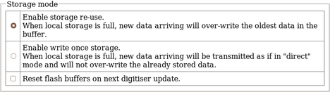
Selecting the Reset flash buffers on next digitiser update check-box will cause all data in the flash storage to be erased and the read pointers to be reset. Use with caution: data will be erased.
The next section controls two settings associated with data transmission:
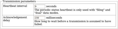
When the digitiser is in the “filing” or “dual” transmission modes, regular heart-beat messages are sent. This allows software such as Scream! to be aware of the devices even though they are not sending sampled waveform data. The frequency of these messages can be set to an integer number of seconds using the Heartbeat interval text field.
When the digitiser is in the “adaptive” or “FIFO” transmission modes, special action is taken if data cannot be transmitted. The acknowledgement delay field controls how long the digitiser waits for an acknowledgement packet before assuming that the link has failed. This should be set to an integer number of milliseconds.
The “Ports” section of the web page allows control of the baud rates of the digitiser's serial ports:
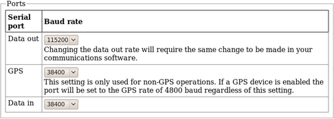
For a stand-alone digitiser or digital instrument, the “GPS” and “Data in” ports are exposed on external connectors. The “Data out” port is assumed to be connected to the CMG-EAM, CMG-DCM or CMG_NAM and the rate set here must match that set for the appropriate serial port (see section 9.1 for details of reconfiguring serial ports).
If a stand-alone digitiser or digital instrument is fitted with a Lantronix Ethernet or WiFi option, it uses the “Data out” port settings for its internal communications with the digitiser. Changing the associated baud rate requires making a network connection to the Lantronix unit's web interface and selecting the matching baud rate from its control page.
Note: For CMG-DAS systems, the digitiser's “Data out” port is connected internally to the CMG_EAM module's “Port A” and both ports must use the same Baud rate. The digitiser's “Data in” port is used to provide a console for the digitiser (without interrupting seismic data transmission) and is connected internally to the CMG_EAM module's “Port B”. Again, both ports must use the same Baud rate. The digitiser's “GPS” port is connected to the CMG_EAM module's “Port C”. This connection can be used in two ways: the CMG-EAM module can share with the digitiser the data from the physical GPS receiver and use it as an NTP clock source (see section 6.3 on page 64); or, alternatively, the CMG-EAM module can be synchronised to another time source (such as Internet NTP) and provide NMEA signals to the digitiser module. In either case, The digitiser module's “GPS” port and the CMG-EAM module's “Port C” must use the same Baud rate.
Digitiser clock is displaced by more than 5 minutes from the system clock. (Plus 7 minutes.)
This section of the page is shown here without the warning:
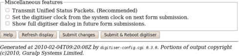
The first check-box enables the transmission of Unified Status Packets. Unified Status Packets are a machine-readable representation of the data carried in the normal, human-readable status streams and allow programs such as Scream! to access complete and consistent state-of-health information regardless of any status stream customisations.
The second check-box allows the one-time re-synchronisation of the digitiser to the EAM's system clock. The third toggles display of the underlying dialogue with the digitiser, as described at the beginning of this section.
Note that, as with all web interfaces, options selected on this screen will not take effect until the page is submitted.
Extra buttons at the bottom of this page allow the refreshing of the web page display with up-to-date information and offer the opportunity to reboot the digitiser.
Note: Some digitiser configuration changes require the digitiser to be rebooted before they will take effect. Please consult the digitiser manual for more information.
7.2 Configuring digitisers from the command line.
Platinum provides a tool, data-terminal, which allows direct access to the command-line of any serially attached digitiser. This gives the greatest level of control but also involves the most complexity.
Interactions with the digitiser's command-line are beyond the scope of this document: please consult the relevant digitiser manual for information on this topic. This section discusses use of the data-terminal tool only.
To invoke the tool, enter the command
data-terminal
You will be presented with a menu listing all digitisers to which a connection can be made:
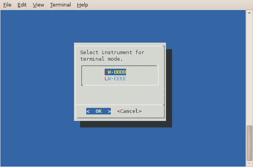
Select the required digitiser from the menu. The data-terminal program will suspend any service running on the associated port and start a minicom session with the correct communications parameters already set.
The use of minicom is described in section 14.4. When you have finished configuring the digitiser, key  +
+ then
then  to exit. Any previously running service will be restarted.