Chapter 7. Sample-clock Timing

All Platinum systems offer a choice of timing modes. The modes available on the Affinity are:
Direct GPS – the sample clock is trained directly to GPS time, as determined from an attached GPS receiver;
PTP – the sample clock is trained to system time, as synchronised using the Precision Time Protocol (PTP);
NTP – the sample clock is trained to system time, as synchronised using the Network Time Protocol (NTP);
Manually set – the sample clock is manually set by the operator; and
CD24/DM24 with GPS – the sample clock is trained to system time, which is synchronised to incoming Universal Status Packets (USP) from an attached CD24 or DM24 digitiser (which is, in turn, assumed to be synchronised to GPS time).
For the Affinity, the recommended timing mode is Direct GPS. This offers the highest accuracy of all available options.
The Platinum manual describes Direct GPS mode, NTP mode, Manual mode and CD24/DM24 with GPS modes. This chapter duplicates the Direct GPS mode section and provides information about PTP mode, which is unique to the Affinity.
To configure the Timing mode using the web interface select:
Configuration → Data handling → Timing
The resulting screen first offers a button,  , which allows the display time-zone to be set from an extensive list. Note that this does not affect the sample clock – just times and dates displayed in the web interface and log-files.
Clicking the
button shows the following window.
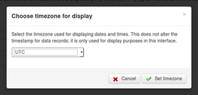
Select the required time-zone and then click  to save your choice.
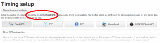
Beneath the time-zone selection button is a paragraph that specifies the currently-selected timing mode, as shown below:
You can visit each of the tabbed screens without changing the mode. Each tabbed screen has its own “Set timing…” button, which saves any changes made to data in put fields on that tab and sets the relevant mode, if it has changed.
7.1 Direct GPS mode
7.1.1 Configuration
This is the recommended mode. It requires a physical GPS receiver to be connected.
From the Timing setup screen, clicking the  button displays the following tab:
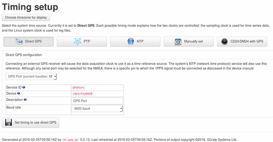
The drop-down menu allows you to select the port to use as a GPS input. Although you can select from the Auxiliary serial port, the Data port, the GPS port and the Sensor Control Port A, this should be left set to GPS port in almost every circumstance. Please contact Güralp support if you decide to change this setting. The menu displays the currently-selected port function for each listed port.
Below the drop-down menu are:
The Service ID: The displayed ID is used as the service name for the serial port. Restarting this service will restart the serial port's function. It is also used to name configuration files and for log messages.
The Device name: This displays the path to the Linux device node. It is only shown for information and for users who wish to interact with ports on the command line.
The Description: This describes the port. It depends on the setting chosen in the drop-down menu.
Baud rate: This drop-down menu allows you to select the line speed of the selected serial port. For Güralp GPS receivers, this should be set to 4,800 Baud. Some combined GPS/Glonass receivers may require higher line speeds. Please contact Güralp support if in any doubt.
Once any required changes have been made, click  to save your changes (if any) and set the system to use the Direct GPS mode.
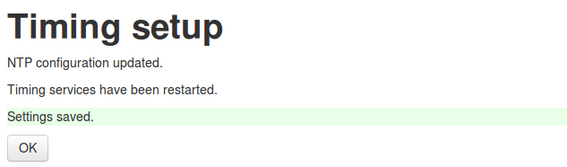
An acknowledgement screen is displayed:
7.1.2 Diagnostics
When in Direct GPS mode, the main status screen acquires an extra tab displaying the GPS receiver status:
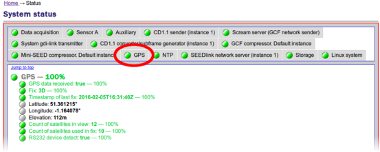
This tab displays various pieces of information about the GPS receiver, including the Fix type (which must be 3D for correct operation) and the number of satellites currently in view.
Note: There must be at least four satellites in view in order to obtain a 3D fix. If the number of satellites is consistently less than four or if the fix is 2D or none, check that “GPS data received” is true and, if it is, consider re-positioning the GPS receiver so that it has an unobstructed view of the sky. If you still have problems obtaining a 3D fix, please contact Güralp technical support for advice.
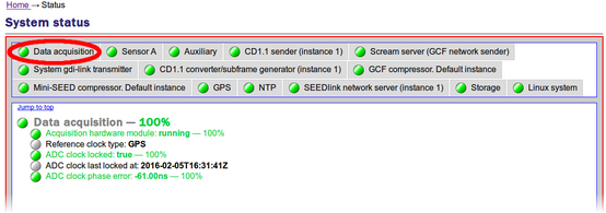
The Data acquisition tab of the main status screen also indicates that the timing mode is GPS, in the Reference clock type field:
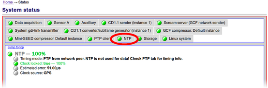
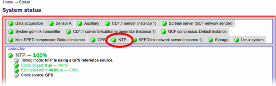
…and the NTP tab shows the timing source to be GPS:
7.2 PTP mode
IEEE 1588-2008 Precision Time Protocol (PTP) is a protocol used to synchronise clocks throughout a computer network. On a local area network, it achieves clock accuracy in the sub-microsecond range, making it significantly better than NTP but not as good as accurate as GPS.
The PTP implementation on the Güralp Affinity (ptp4l) requires that a grandmaster clock be present on the same network segment as the Affinity (or all the routers between the grandmaster clock and the Affinity must be configured to allow multicast UDP packets on 224.0.1.129 and 224.0.0.107 for IPv4 or FF0x::181 and FF02::6B for IPv6).
7.2.1 Configuration
From the Timing set-up screen, clicking the  button displays the following configuration screen:
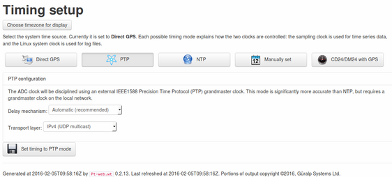
PTP requires very little configuration. The following parameters can be adjusted:
Delay mechanism: The options are:
E2E – end-to-end mode is appropriate for basic networks;
P2P – peer-to-peer mode is appropriate for networks which have been optimised for PTP; and
Automatic – this mode automatically detects whether to use E2E or P2P. It is the recommended setting.
Transport Layer: The options are
IPv4 (UDP Multicast);
IPv6 (UDP Multicast); and
802.3 (raw Ethernet).
Unless you have very specific requirements, and you understand the implications, this should be left set to IPv4.
Once any required changes have been made, click  to save your changes (if any) and set the system to use the Direct GPS mode.
7.2.2 Diagnostics
When in PTP mode, the main status screen acquires an extra tab displaying the PTP status:
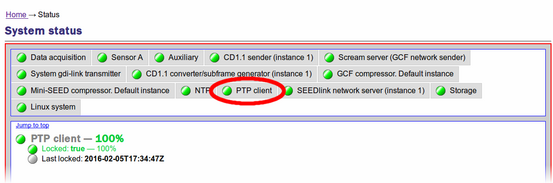
This tab simply displays the current lock status and the time that a lock was last achieved.
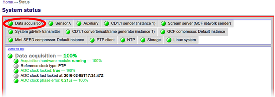
The Data acquisition tab of the main status screen also indicates that the timing mode is PTP, in the Reference clock type field:
The NTP tab also changes to show that the timing mode is PTP. The message “NTP is not used for data” is not an error: it is there to remind you that the sample clock is disciplined directly by PTP.