Chapter 4. Operation guide
4.1 Principals of operation
The Güralp Orcus OBS contains two seismometers: a 5T strong motion triaxial accelerometer, and a 3T weak motion triaxial seismometer.
For details of the Güralp 3T sensor you are referred to the specific manual, which can be downloaded from: https://www.guralp.com/documents/MAN-030-0001.
For details of the Güralp 5T sensor, you are referred to the specific manual, which can be downloaded from: https://www.guralp.com/documents/MAN-050-0001.
The Affinity manual represents a detailed Users' Guide for the digitiser, which can be downloaded from: http://www.guralp.com/documents/MAN-AFT-0001. This manual provides details of the features which are unique to the Affinity, including configuration and operation of the built-in ADCs and the connector pin-out.
 The Güralp Affinity runs the Platinum operating system, which is common to many Güralp data acquisition modules, including the EAM, the NAM and the legacy DCM. Platinum provides rich web and command-line interfaces to configure, control and monitor all data storage, protocol conversion, and communications functions. These features of the Affinity are all described in the Platinum manual, MAN‑EAM‑0003, which is available to download at the following link http://www.guralp.com/documents/MAN-EAM-0003.
4.2 Power monitoring
4.2.1 Operation
The Orcus OBS includes a power monitoring and control facility which can measure and switch the current flowing to and from the various components of the system. This can be accessed via the configuration interface of the Affinity using a web browser.
The configuration interface of the Affinity is described in detail in MAN‑AFT‑0001. The following description assumes some familiarity with the use of this interface.
To access the power monitoring and control facility, select “Digital I/O” from the Control menu. The screen that appears shows a table where each row refers to a particular power output or input, known as a line.
For each line, the current status is displayed along with a set of buttons which can be used to change the configuration or state of the associated line.
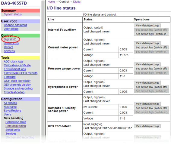
The table identifies lines by their user names but each line also has a system name. User names can be re-configured if desired. For example, the second line displayed in the diagram has the user name “Current meter power” but this can be changed according to the operator’s preferences. See section 4.2.3.1 for details.
Next to the name of each line is displayed the line's status: low (off) or high (on). A line can be turned on and off with the “Set output high” and “Set output low” buttons.
Note: The Orcus OBS systems are shipped with many power lines set low (turned off) in order to minimize the power consumption. The default status of each line at power-up can be configured. See section 4.2.3.2 for details.
Note: The leveller power is switched off by default when the system is powered up. To level the bowl, switch the leveller line on.
4.2.2 The details view
A summary of the state of each line is shown in the Status column but further details are available by clicking the  button.
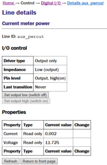
Most of the features of this screen duplicate those on the main “Digital I/O” display. A  button provides quicker access to the latest figures if a line is being monitored in real time.
The allocation of lines to hardware components for the CMG Orcus OBS is as follows:
Line (system name) | Function |
aux_powerout | Current meter power |
auxb_powerout | Pressure gauge power |
eth_pwrout | Hydrophone 2 power |
gps | Compass / Humidity sensor power |
sensor_A | Sensor A (3T) Power |
sensor_B | Sensor A (5T) Power |
usb0_hvpwrout | Hydrophone 1 power |
usb1 | Leveller |
Note: The main incoming power is fed through a power conditioning circuit before being routed to the power control sensors, so it is the conditioned voltage that is monitored, not the supplied voltage.
4.2.3 Configuration
To configure the user names of the power lines, select “All options” from the “Configuration” section of the main menu:
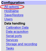
From the resulting menu, select GPIO labels and power switch settings. The following screen is displayed, from where it is possible to edit the user labels of the power lines:
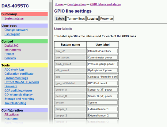
4.2.3.1 Power line labels
To change the name of any power line, alter the User label field in the table shown above and then click the  button at the bottom of the page to save your changes.
Note: No immediate changes happen when this page is submitted. Changes only take effect after a re-boot of the unit.
4.2.3.2 Power up status
To change the status of any power line at power-up, navigate to the Power up tab of the previous screen.
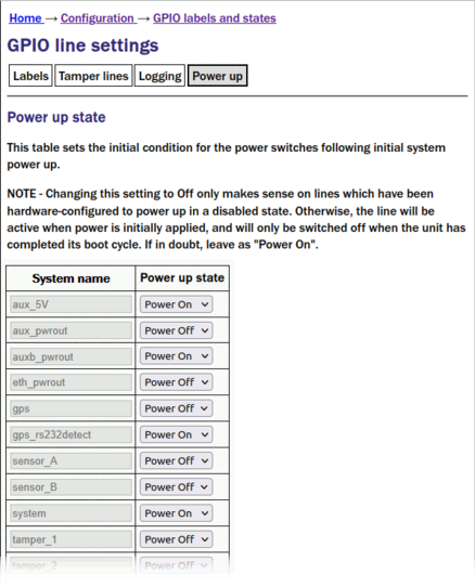
The drop-down menus can use used to configure the power-up state of each of the lines. Remember to click the
button at the bottom of the page to save any changes.
4.3 Data acquisition configuration
The configuration interface can be used to configure the ADC in the Affinity. The interface for external digitisers and digital instruments is described in the Platinum manual MAN‑EAM‑0003. This section describes the interface for the ADC in an Affinity.
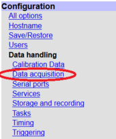
To configure the ADC using the web interface, select
Configuration → Data handling → Data acquisition
The Data acquisition configuration screen is displayed:
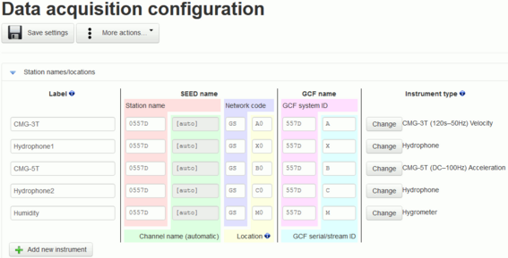
This screen has three parts: “Station name/locations”, “Synchronous channels” and “Multiplexed channels”. Each section can be expanded (shown) or contracted (hidden) by clicking the blue arrow symbols,  and
and  .
.
4.3.1 Station names/locations
This section is used to configure the logical instruments which are being associated with the ADCs. Each row represents a logical instrument and additional rows can be added as required using the  button.
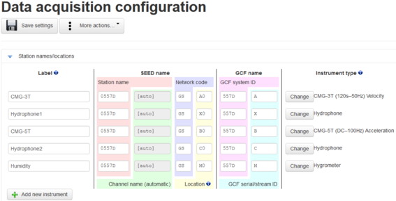
For each logical instrument, the following attributes are displayed:
SEED name – these four-part values are used for naming channels in miniSEED, SEEDlink, CD1.1 and some other protocols. The four parts are:
Station name – initially based on the serial number of the Affinity but can be altered here as desired.
Channel name – automatically determined from the Instrument type
Network code – option—leave blank if not required
Location – automatically populated but can be over-ridden if desired
GCF name – these values are used for naming channels saved or transmitted using GCF protocols, such as Scream, BRP and GDI.
GCF system ID – initially based on the serial number of the Affinity but can be altered here as desired.
GCF serial/stream ID – automatically populated but can be over-ridden if desired
Instrument type – The instrument type can be chosen from the extensive menu which is displayed when you click the
 button.
4.3.2 Synchronous channels
For each of the four main synchronous channels, this section allows you to select the component letter used for stream naming, the channel gain to be applied and the sample rate(s) to be generated.
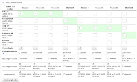
Channel gains from unity to ×64 are available in binary steps. To change a channel gain, click the appropriate  button.
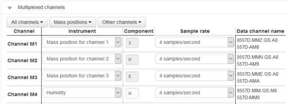
4.3.3 Multiplexed channels
This section displays one row for each available multiplexed channel.
The display can be filtered to show subsets of the channels:
The
 button shows only channels designated as mass position channels, typically M1, M2 and M3.
The
 button hides the mass position channels and shows all others.
The
 button displays every channel.
For each multiplexed channel, the associated instrument and component are shown, along with a drop-down menu for selecting the sample rate and the associated automatically-generated SEED name (in S.C.N.L. format) and GCF name.
The available sample rates for multiplexed channels are 1, 2, 4, 5, 8 or 10 samples per second. Each channel can also be switched off using the “Sample rate” drop-down menu.
4.4 Serial ports
The 3T SoH, Leveller, Compass, Aquadopp and Pressure Gauge each have a serial output and are connected to the Affinity’s serial inputs. For the Compass, Aquadopp and Pressure Gauge, the Affinity forwards the data via the Ethernet interface using a serial-to-IP converter implemented in the Platinum software. Each of those serial devices has a TCP port in order to allow connections to the devices using either a terminal emulator like PuTTY or the supplier’s software.
Device | Port | Baud rate | TCP port |
3T SoH | SenAPort | 38400 | N/A |
Aquadopp | DataPort | 9600 | 2102 |
Compass | GPSPort | 19200 | 2101 |
Instrument leveller | SenBPort | 38400 | N/A |
Pressure Gauge | AuxPort | 9600 | 2103 |
Serial ports are configured using the web interface:
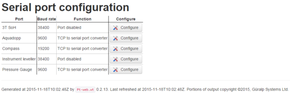
To access the configuration screen, select:
Configuration → Data handling → Serial ports
The  button next to each port allows configuration of the port function and any associated parameters. For ports configured to be serial-to-TCP converters, the available parameters are the Baud rate, the bind address and the TCP port on which to listen.
Note: As these systems have only one physical network interface, the bind address should be left blank.
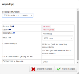
Click  after making any changes.
4.5 Sample-clock timing
The Affinity offers five different timing modes.
To access the configuration screen, select:
Configuration → Data handling → Timing
To select a mode, click one of the buttons:
 ,
,  ,
,  ,
,  or
or 
The screen changes to show the appropriate configuration parameters. Complete the configuration and then click the “Set timing to…” button at the bottom of the screen.
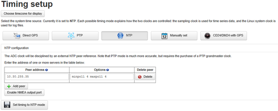
The most common timing mode for an Affinity in an Orcus is NTP. To configure the Affinity to use NTP, it is only necessary to add the address(es) of one or more peers. The default options are almost always sufficient but advaned users may wish to study the NTP documentation at https://linux.die.net/man/5/ntp.conf.
After making any changes, click the
button to save the new configuration.
4.6 Seismometer control
The 3T can be controlled using the command line or the web interface.
4.6.1 Control via the command line
To access the command line, it is necessary to make an SSH connection. The ssh command is installed by default on most Linux systems. For Windows users, Güralp recommend the free terminal emulation software PuTTY, available from http://www.chiark.greenend.org.uk/~sgtatham/putty/).
The connection procedure is described in detail in MAN‑AFT‑0001, section 4.2. The examples below assume the use of PuTTY.
Once you have the IP address, start PuTTY by choosing it from the “Start” menu or double-clicking on its icon. You will be presented with the following screen:
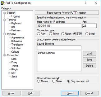
Enter the IP address of the Affinity into the Host Name (or IP address) field, check that SSH is selected as the Connection type and then click the  button.
The first time you use SSH to connect to any host, you will be asked to verify the “host key”:
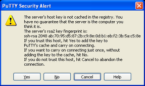
This is normal (simply click  to dismiss the dialogue) but, if you are ever asked this again, it means that either the host key of the Affinity has changed – perhaps because of a firmware upgrade – or there is a network address conflict or, worse, a security problem on your network.
You will now be prompted for a login name: the default is root. Type this at the prompt and key  . You will next be prompted for a password: the default password is guralp3. Note that no characters will be echoed to the screen as you type the password.
4.6.1.1 The 3T’s SoH processor
The 3T’s State-of-Health (SoH) processor controls the mass operations: locking, unlocking and centring. The processor has a command-line interface. To use this, log on to the Affinity’s command line, as described in the previous section, and then type the command openport:
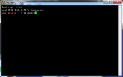
The following window will appear.
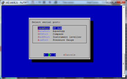
Select SenAPort- 3T SoH from the menu. This opens the command line of the 3T’s SoH processor.
4.6.1.2 Mass locking
Connect to the command line of the 3T’s SoH processor, as described in section 4.6.1.1. Type lock in the terminal window and key
.
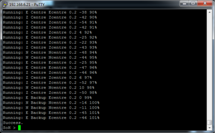
The progress of the locking operation will be reported in the terminal window:
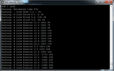
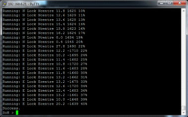
When locking complete, the terminal will report the line, “Success”.
Caution: It is essential to lock all components any time you need to move the Orcus OBS. The 3T sensor’s components have very delicate parts that can easily be broken during transit if not locked. During installation or recovery, the sensor always has to be locked. Only when the sensor has been deployed permanently on the seabed can it be safely unlocked.
4.6.1.3 Mass unlocking
Caution: Before unlocking the masses, the Orcus must be in a stable position and the bowls must be levelled, as described in section 4.6.1.5 and section 4.6.2.2. Failure to observe this can result in severe damage to the instrument.
Connect to the command line of the 3T’s SoH processor, as described in section 4.6.1.1, and type the command unlock. The progress of the command will be shown in the terminal window, as with locking.
4.6.1.4 Mass centring
Mass centring is the fine adjustment of the individual tilt-bases so that the feedback circuitry can maintain the masses in the central position without providing assymmetrical drive to the feedback coil. Mass centring reduces power consumption, reduces system self-noise and optimises clipping levels.
Masses may need frequenct centring over the first week of operation, while the instrument acclimatises. It is important to monitor the mass position outputs during this period and the centre the masses if any exceeds arouund 25% of full-scale. Further centring may be required at increasingly long intervals during the entire deployment so continuous monitoring is essential. Automatic monitoring and centring is possible: please contact support@guralp.com for details.
Caution: Mass centring must only be performed when the Orcus is in a stable position, the bowls have been levelled, as described in section 4.6.1.5 and section 4.6.2.2, and the masses unlocked, as described in section 4.6.1.3.
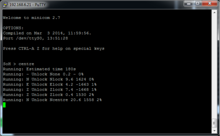
To centre the masses, connect to the 3T’s SoH command line, as described in section 4.6.1.1, type centre in the terminal window and key
. The progress of the centring process will be reported in the terminal window:
4.6.1.5 The levelling system
The Orcus levelling system controls the gimbal bowls that contina the three 3T’s component sensor. It is implemented by a processor with a command-line interface. To connect to the levelling system’s command line, log on to the Affinity’s command line, as described in the previous section, and then type the command openport:
The following window will appear.
Select SenBPort- Instrument leveller from the menu and clcik OK. This opens the command line of the leveller’s processor.
Note: The leveller is off by default when the Orcus OBS is powered up. To switch it on, please follow the procedure described in section 4.2.1.
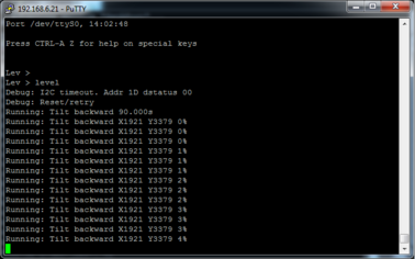
To level the bowl, type level at the prompt and key
. Progress will be shown in the terminal window:
Other commands which can be used at this prompt are given in the table below. Commands are not case-sensitive.
Command | Description |
HELP | Entered at any time, this will list the commands available in the current mode. HELP <cmd> will print a short summary of the command's action and parameters. |
DATUM | Returns the system (tilt and rotation) to the datum positions. |
DATUM TILT | Tilts the system to the tilt datum position. |
DATUM ROT | Rotates the system to the rotation datum position. |
LEVEL | Levels the full system. |
LEVEL TILT | Level the system on the tilt axis only. |
LEVEL ROT | Level the system on the rotation axis only. |
LEVEL HUNT | Searches for a better level position on an already-levelled unit. |
DRIVE TILT FWD n | Drive the tilt (TILT) or rotation (ROT) motor forwards (FWD) or backwards (REV) for n seconds. n can be given as a decimal value. If n is omitted, drive the specified motor as far as its limit switch. To stop at any time, key |
SWITCHES | Test the limit switches. To interrupt, key |
HW_SCAN | Reports the tilt angle of other devices (e.g. MEMS tilt-meter, compass) using the I²C protocol. |
TILT | Report the current body tilt, measured as an angle from the vertical. |
TILT.BASE | Report the tilt of the base plate. |
TILT.BASE.X | Report the tilt of the base plate along the x-axis. |
TILT.BASE.Y | Report the tilt of the base plate along the y-axis. |
DEBUG TRUE | Enables the output of debugging information |
DIAG | Enables diagnostic commands. |
QUIT | Exit diagnostic mode. |


4.6.2 Control via web page
The Control menu of the web interface is a dynamic menu with content that changes depending on the underlying hardware. Selecting
Configuration → Control → Instruments
takes you to the Instrument Control page. From here, one can query mass positions, lock, unlock and centre the sensor masses and perform bowl levelling.
The Orcus’ sensors as listed as CMG-3T for the seismometer and CMG-5T for the accelerometer.
4.6.2.1 Mass locking and centring
To control an instrument using the web interface select:
Configuration → Control → Instruments
The following screen is displayed:
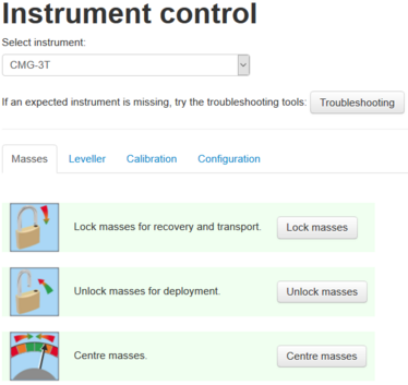
Select CMG-3T from the Select instrument drop-down menu, and click to the Masses tab, if necessary. Click on the relevent button,  ,
,  or
or  to perform mass locking, unlocking and centring, respectively.
4.6.2.2 Leveller
To control the leveller using the web interface select:
Configuration → Control → Instruments
and click to the “Leveller” tab.
The following screen is displayed:
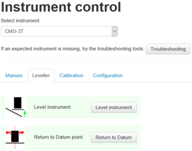
Click on the  button to level the instrument.
Click on the  button to return the instrument to its initial position. For more sophisticated control of the levelling system, please see section 4.6.1.5.
Note: These controls invoke the appropriate digitiser commands. An indication of success means that the digitiser has accepted the command but does not imply that it has completed correctly.