Chapter 8. Pre-deployment procedures
8.1 Charging batteries
Follow the instruction in Section 5.4 to charge the batteries correctly before the deployment.
8.2 Attach Ballast and Burn-Wire System
8.2.1 Locate System on Ballast
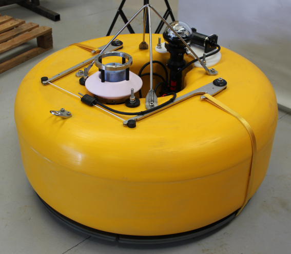
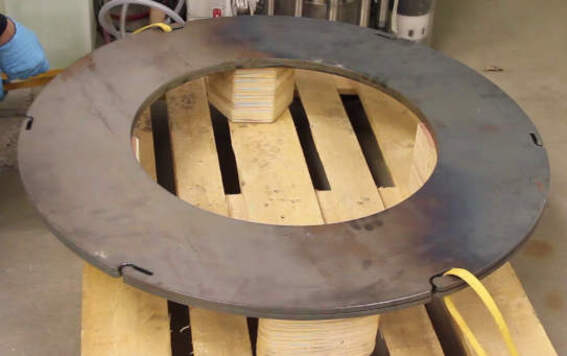
The Aquarius system (comprising of pressure vessel, buoyancy and ancillaries) sits in/on-top-of twin steel ballast rings. The Aquarius system is lowered (by the lifting frame) down on to new ballast rings.
The easiest way to approach this task is to raise the plates off the ground with suitable blocks first, to ensure the lowered Aquarius system sits down on to the ballast plates directly rather than resting on the ground. This can make aligning the circular ridge on the Aquarius buoyancy with the inner circle of the ballast easier, and reduces the force required by the burn-wire tensioning tool (which would otherwise be required to lift the ballast plates before tensioning occurred).
The ballast plates each have three pairs of opposing slots cut into their perimeters at equal intervals, each with a different slot depth. These allow for three different pre-tension settings for the straps suspending the ballast plates, to account for manufacturing variances in the straps and buoyancy.
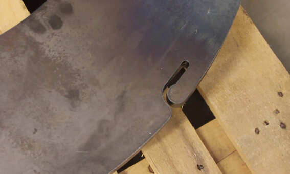
It is essential to ensure that the slots are correctly aligned between the two ballast plates before proceeding.
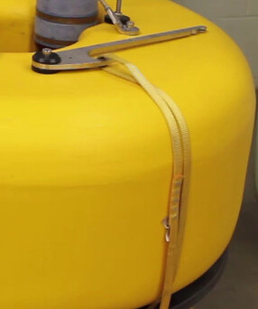
Select an opposing pair of slots in the ballast plates (if in doubt, pick the middle pair) and insert the two strap loops into these slots.
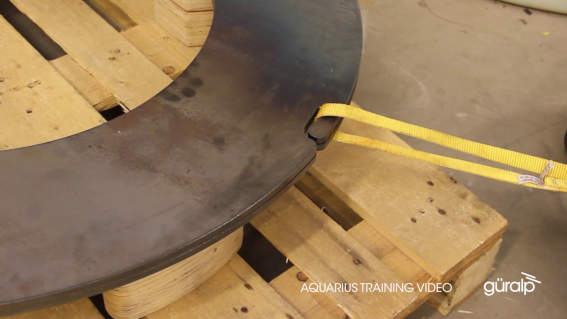
Ensure that the strap loops are located as far into the slots as possible, so they cannot slip out when tension is applied.
Now carefully lower the Aquarius system onto the ballast plates.
As the system is being lowered, observe that the protruding circular rim in the underside of the buoyancy aligns and locates properly into the inner circle of the ballast plates. Therefore, the buoyancy is permitted to sit down fully into the ballast plates.
In addition, ensure that the Aquarius system is rotationally aligned with the chosen slots in the ballast plates, such that the straps will travel vertically from the ballast plate slots to the hooks in the burn-wire arms.
8.2.2 Tension Burn-Wire
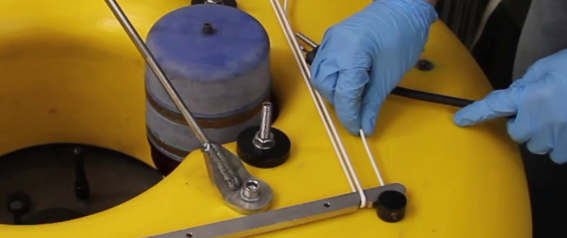
With the Aquarius system located on ballast plates, ensure that the two strap loops are hooked securely over the burn-wire arms. When brought together, the arms should rest equidistantly from the lifting frame (and the centre of the Aquarius) as shown below.
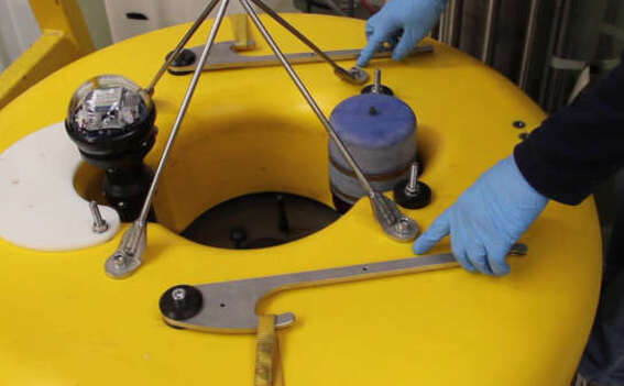
If the arms are not equidistantly spaced, this indicates that either;
the buoyancy is not properly located into the ballast plates
the Aquarius is not rotationally aligned with the chosen strap slots on the ballast rings.
In either case, the Aquarius and ballast arrangement must be adjusted.
The arms must be tensioned to permit the burn-wire to be installed. Use the supplied burn-wire tensioning tool to achieve this.
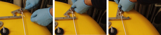
Locate the white wire loop around the smaller/inner notch in one of the arms as shown below:
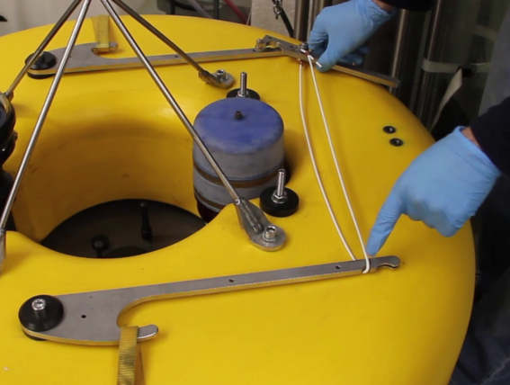
Then align the tip of tensioning tool into the smaller/inner notch in the opposing arm as shown below. Ensure that the retaining washers straddle the arm to prevent the tensioning tool slipping.
Now pivot the tensioning tool around the inner/smaller notch to bring the two arms together. Take care the ensure that the wire loop passes around the arm and pivot point.
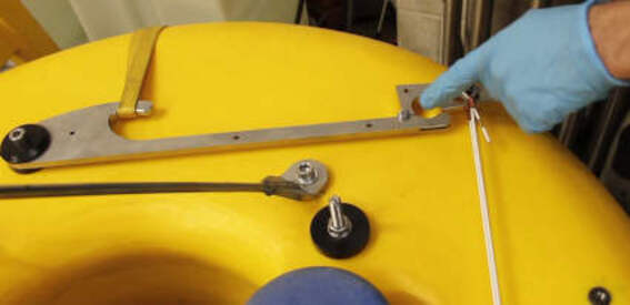
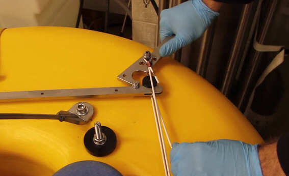
With the arms tensioned with the tensioning tool, insert each end of a new burn-wire into the larger/outer notch of each of the arms.
Ensure that the burn-wire itself passes through the slots cut into the arms.

With the burn-wire in place, now release the tensioning tool to transfer the tension of the ballast release system from the tool to the burn-wire itself. Ensure that the tensioning tool wire loop passes cleanly around the burn-wire ends and does not force them from the arm notches.
As the tensioning tool is removed, the burn-wire passes completely through the tensioning tool wire loop, including the central potted junction node and cable.
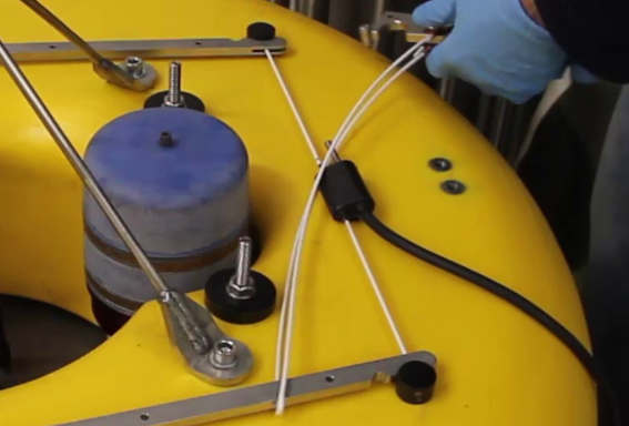
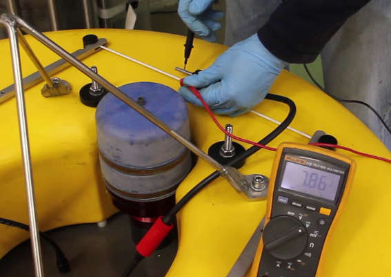
Finally, after cleaning and applying grease as required the two way Subconn burn-wire connector may be mated with the cable loom. The electrical operation of the burn-wire should be verified by manually activating the burn-wire from Discovery and assessing the anode to cathode voltage with a multimeter.
8.3 Time synchronization and configuration
Follow the instruction in Section 7.2.2 to configure the PTP settings. If using the deck unit, PTP must be set in unicast mode, with I.P. 192.168.0.10.
Use the “OBS Command & Control” widget (see Section 7.1.3.2) to obtain the time offset when the PTP reaches a good stability. Offset should be 0ms before deployment.
Follow the procedure in Section 13 when configuring the Aquarius using the web page (see Section 7.2) and the “OBS Command & Control” widget (see Section 7.1.3, page 35). This procedure also check all sensors in the Aquarius and the Burn-Wire, so the APG and the Burn-Wires need to be connected using the relevant cable.
8.4 Acoustic communication check
It is important the verify the operation of the acoustic modems before deployment. Although not optimal, it is possible operate the modems out of water with the use of a suitable acoustic coupler. One such aluminium coupler is supplied with your system.
By placing the coupler on the Aquarius modem transducer, the topside Dunker modem may then be stacked on top and temporarily held or secured in place.
Set both modems to power levels suitable for operation in air, refer to Section 7.1.3.3.
Caution: Remember to set the acoustic settings of both modems appropriately for the intended operational depth before deployment.
Follow the instruction in Section 7.1.3.4 to verify whether the acoustic link is properly working. Note that only low data transfer speeds will be possible and the failure rate of acoustic transactions may be high. This is normal when out of water.
8.5 Final assembling
When time synchronization, configuration and test of the Aquarius has been completed, the Ethernet and serial cable can be disconnected from the OBS top lid. Place the Seacon Hummer series dummy cap and screw the locking sleeve down. Check also connection of the accessory and Burn-Wire cable by the 8 way Subconn Mini series connector.
Check that all the other caps have been properly screwed down with all the O-rings in place.