Chapter 12. Appendix 3 – Connector pin-outs
12.1 Ethernet
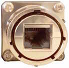
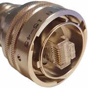
This is an Amphenol RJField-series 8P8C connector. It consists of a standard ISO 8877 8P8C modular socket (often called RJ45) in a bayonet mounting compatible with MIL‑DTL‑26482 (formerly MIL‑C‑26482). |
|
Pin | 10BASE-T & 100BASE-TX | 1000BASE-T |
1 | Transmit Data + | BI_DA+ |
2 | Transmit Data - | BI_DA- |
3 | Receive Data + | BI_DB+ |
4 | not connected | BI_DC+ |
5 | not connected | BI_DC- |
6 | Receive Data - | BI_DB- |
7 | not connected | BI_DD+ |
8 | not connected | BI_DD- |
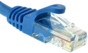
| This connector accepts unmodified ISO 8877 8P8C modular connectors (often called RJ45 connectors or Ethernet “Cat 5/6” connectors). |
|
When used in hostile environments, a standard Ethernet cable can have a mating environmental shield (Amphenol part number RJF6MN) fitted. |

12.2 Power
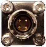
This is a standard 4-pin military-specification bayonet plug, conforming to MIL‑DTL‑26482 (formerly MIL‑C‑26482). |
|
Pin | Function |
A | Ground |
B | 10-36 V DC input |
C | not connected |
D | not connected |
| Wiring details for the compatible socket as seen from the cable end (i.e. when assembling). |

Caution: Observe the correct polarity when connecting the power supply. The red lead (from pin B) must be connected to the positive terminal, typically labelled ‘+’, and the black lead (from pin A) must be connected to the negative terminal, typically labelled ‘-’. An incorrect connection risks destroying the digitiser, the power supply and any connected instruments.
12.3 GNSS/serial
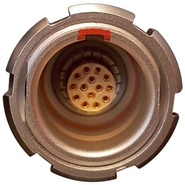
This is a 14-pin LEMO EEG.1K socket. Suitable mating connectors can be found in the LEMO FGG.1K.314 range.
|
|
Pin | Function |
1 | Ground |
2 | not connected |
3 | Ground |
4 | Debug (serial) receive |
5 | Debug (serial) transmit |
6 | not connected |
7 | GNSS power |
8 | GNSS pulse-per-second signal – RS-422 positive |
9 | GNSS receive – RS-422 positive |
10 | GNSS transmit – RS-422 positive |
11 | GNSS transmit – RS-422 negative |
12 | not connected |
13 | GNSS pulse-per-second signal – RS-422 negative |
14 | GNSS receive – RS-422 negative |
| Wiring details for the compatible plug, FGG.1K.314.*, as seen from the cable end (i.e. when assembling). |
