The Güralp Fortimus is a Fortis triaxial accelerometer combined with a Minimus digitiser. The Minimus acquires data from – and allows direct control of – the Fortis analogue instrument.
The labelled parts are:
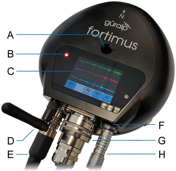
A
Hole for mounting bolt
E
Power connection
B
Status LED
F
Cover for SD card
C
Touch-screen display
G
Ethernet connection
D
WiFi antenna
H
GNSS connection
The hard-anodised aluminium casing protects the instrument from water, allowing it to be deployed in a range of environments. Installation is simple, using a single fixing bolt to attach the sensor to a hard surface. If required, you can also level the sensor using its adjustable levelling feet. An integrated digital bubble-level – available in the display menu – provides quick visual feedback during levelling.
3.1.1 Liquid Crystal Display
The Fortimus is equipped with a multi-touch sensitive, 2.4 inch, full colour LCD touch-screen which shows waveforms and a virtual instrument level. Its menu system allows control of instrument state of health, gain settings and network configurations.
The LCD features are described in detail in chapter 5.
3.1.2 LED indicator
The Fortimus has an LED indicator on the upper surface, which provides status and configuration information.
This information is encoded in sequences of coloured flashes. In general, red flashes indicate that initialisation is in progress or that the instrument has encountered a problem, green flashes indicate normal operation and blue flashes show trigger activity. The various codes are:
One quick red flash followed by a one second pause: the removable microSD card is present in the Fortimus’ external slot, but no fixed microSD card is present inside the Fortimus.
Two quick red flashes followed by a one second pause: the fixed microSD card is present inside the Fortimus but no removable microSD card is present in the Fortimus’ externally-accessible slot.
Three quick red flashes following by a one second pause: both microSD cards are present but either the GNSS receiver is disconnected or the GNSS lock is not sufficiently accurate.
A green flash every four seconds: this is the standard operating heartbeat. GNSS and both internal and external microSD cards are present, which indicates that the Fortimus can be successfully deployed and left to record data.
Note: Depending on the digitiser’s recent history, it can take up to ten minutes to reach this state after power-up.
1 blue flash: a trigger event has been detected.
3.1.3 Bluetooth connectivity
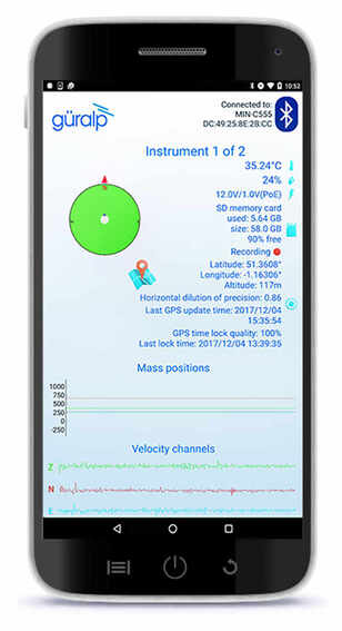
The Fortimus features Bluetooth connectivity, allowing sensor and state-of-health data to be monitored using the Güralp GüVü app (see Section 3.4) running on an Android mobile phone or tablet.
Bluetooth can be disabled via software to save processor usage but the hardware module cannot be switched off. BLE (Bluetooth Low Energy) technology is used to minimise the power requirement. The Bluetooth transmitter/receiver is in permanent standby mode and always ready to receive a connection from a phone or tablet.
See Chapter 8 for further details on connecting to the Fortimus using a phone or tablet.
3.1.4 MEMS accelerometer
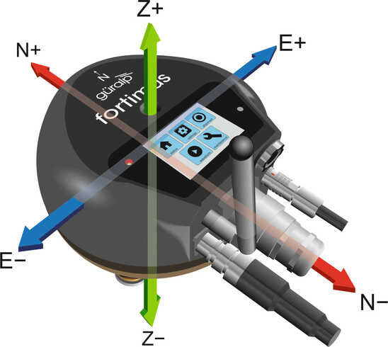
The Fortimus digital accelerometer is equipped with a triaxial Micro Electro-Mechanical System (MEMS) accelerometer with a measurement range of ±2 g. The three axes of sensitivity, Z, N and E, align with those of the main accelerometer outputs and are orientated as illustrated below:
3.1.5 Data storage
The Fortimus uses microSD (non-volatile) memory technology to store seismic data within the instrument. The Fortimus features two such microSD cards in order to provide redundancy; this helps to protect the recorded data in the unlikely event of any corruption or problem with the memory cards. One card is internal and cannot be removed by the customer; the other is hot-swappable and easily accessible without any technical knowledge.
The Fortimus is supplied with two microSD cards that are of equal storage capacity (e.g. two 64 GB cards).
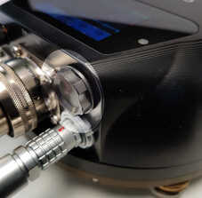
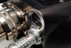
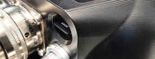
The microSD card is protected by a screw-in cap, located next to the Ethernet connector and above the GNSS connector
Remove the cap by unscrewing it anticlockwise, as shown.
Caution:Finger pressure is sufficient. Do not use tools.
The horizontal edge of the microSD card is now visible
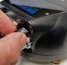
The card slot has a spring lock: pushing the card firmly inwards locks it into place; a second push releases the card so that it can be withdrawn.
Lightly push the edge of the microSD card with a fingertip or soft implement. Once the initial spring resistance has been overcome, the card will partially eject itself.
The card should now protrude enough that it can be grasped and withdrawn.
To replace the card, remove any existing card, as shown previously, and then:
Gently insert the replacement card into the slot with the logo facing upwards and the straight edge of the card on the left, as shown. The card must be perfectly horizontal in order to align properly.
Push the card gently into place until the pressure of the spring lock is felt. If it does not glide into place, remove and start again. Do not force the card.
Check that the card is fully engaged by pressing lightly to unlock it and then pressing to lock it again. The card should be engaged firmly when locked and slide freely otherwise. Ensure the card is locked before proceeding.
Offer the cap to the opening, taking great care to align the screw-thread correctly. Replace the cap by screwing it in clockwise, as shown.
Caution:Finger pressure is sufficient. Do not use tools.
Note: In order to ensure data integrity and security, Güralp only recommend using the supplied industrial-grade microSD cards.
Caution:When the external microSD card is removed, the internal card keeps recording data, unless recording is stopped using . button (see Section 7.10.3). However, when the external card is re-connected, any data written to the internal card while the removable card was absent will overwritten.
3.1.5.2 Internal (back-up) microSD card
The second microSD card is factory-installed in a slot inside the Fortimus.
Caution:The internal microSD card is not accessible by the user. Attempts to remove or replace it will void the Fortimus’ warranty.
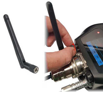
3.1.6 WiFi connectivity
The Fortimus is provided with a Siretta Delta 7A omnidirectional antenna, suitable for both 2.4 GHz and 5.8 GHz networks.
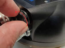
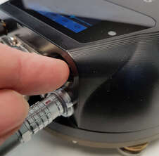
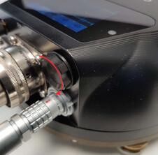
The antenna connects directly to the Fortimus using an SMA connector. It can be removed and replaced with a high-gain, directional antenna if required. To remove, grasp the knurled locking sleeve and turn anti-clockwise, as shown.
See Section 7.5 for further details on how to configure the Fortimus to connect to a wireless network.
Note: It is not necessary to have the antenna fitted if wireless operation is not required.
3.1.7 Web interface
The Fortimus contains on-board firmware that presents monitoring and configuration interfaces. These are accessible through Güralp’s Discovery software (see Section 3.3) or, with the built-in web server, via Discovery's browser interface or any standards-conformant web browser.
The web interface allows a number of instrument monitoring, control and configuration options:
Sensor readings and instrument State-of-Health
Network configuration and authentication
Sensor, timing, and station configuration/information
Remote data-streaming configuration
Local data-storage configuration
Please refer to Chapter 7 for full usage instructions.
3.2 Accessory package
3.2.1 Ethernet cable
The Ethernet connector allows use of 10BASE-T, 100BASE-T or 1000BASE-T networks. The metal gland shell-type connector that connects to the Fortimus is IP68-rated and ensures consistent connection in harsh installation environments. At the other end of the blue Ethernet cable, there is a standard 8P8C modular jack (often incorrectly called an RJ45) for attachment to all common networking devices (e.g. PC, laptop, router, switch, modem etc.).
Please see Section 12.1 for the pin-out and further details.
3.2.2 Compact GNSS receiver and cable
The Fortimus is supplied with a new-generation compact GNSS receiver with an in-built antenna that supports the GPS (Navstar), GLONASS, BeiDou and Galileo satellite constellations.
The receiver comes with a black RS-422 cable that has an over-moulded 14-way LEMO connector. LEMO connectors use an innovative latching mechanism which is different to the bayonet connectors used elsewhere. To mate, simply line up the red marks – one on the chassis and one on the free connector – and gently push the connector into place until they latch together with a click. To disconnect (un-mate), grasp the outer sleeve of the connector and pull gently.
Caution:Do not twist the connector or use any tools.
The Fortimus comes with an adapter to connect the GNSS LEMO connector to a female nine-pin D-subminiature connector (DE9f), which can be used with a standard serial port to allow diagnosis and debugging of the Fortimus using a serial terminal emulator. (See Section 9).
Note:This facility should rarely be required. It is primarily intended for use by the Güralp Support Team to help diagnose any problems with the Fortimus that may be experienced by the user.
A serial-to-USB converter (not supplied) may need to be used to connect to PCs or laptops that don’t have a nine-pin serial connector. Please see Section 12.3 for full pin-out details.
3.3 Güralp Discovery software
Güralp Discovery is a software application for seismometer configuration and control, state-of-health monitoring, and waveform viewing and acquisition.
An important benefit of Discovery is that it allows the user to identify the instruments’ I.P. addresses on a LAN or via a cloud-based or organisational registry server without the need for static I.P. addresses at the stations.
Discovery also provides simple, convenient instrument and data management with access to hardware State-of-Health (SoH), data streaming; GNSS location; response and calibration data.
Discovery can download Fortimus firmware from the Internet and remotely install it onto any connected Fortimus.
3.4 Güralp GüVü Android and iOS app
For added confidence during deployments in the field, Güralp GüVü, a Bluetooth App, displays waveforms, orientation, temperature and humidity data for instant checking of installation integrity.
Please refer to Chapter 8 for installation and usage instructions.