Chapter 10. Controlling CD24 and DM24 digitisers
Note: This chapter applies only to Güralp CD24 and DM24 digitisers. For other models, please refer to the relevant digitiser manuals.
To control a digitiser whilst it is running, either right-click on the digitiser's entry in the list to the left of Scream!'s Main Window (


If you cannot find the setting you want in the Control window, it may be because the digitiser needs to reboot after a change. Try looking in the Configure window instead.
10.1 System
When the Control window is first opened, it will be showing the System pane.

The following controls are available:
Sensor Type : If the sensor attached to the digitiser requires mass control, you can send control commands to it from the Mass Control tab (see below). Which functions are available on the Mass Control tab depends on the Sensor Type you have set in the System tab.
If you change the Sensor Type, you may have to Apply the change, close the Control window, and open a new one to access the Mass Control options.
Output Unified Status packets : Unified status packets are a binary formatted status information packet that is intended for use with Güralp EAM and NAM modules. If your digitiser is connected directly to an EAM or NAM, you should enable this option. Unified status packets report GNSS and channel status every second, so may consume a lot of bandwidth if a digitiser is connected via a bandwidth-restricted link.
Enable GNSS power cycling : If you are using a GNSS unit to receive time signals, but do not experience significant drift in the system's clock (for example, in a stable-temperature environment), you can save power by selecting Enable GNSS power cycling. The digitiser will power up the GNSS receiver at the specified rate, and keep it powered up until a satisfactory timing fix has been achieved. It will then power it down until the next power-up time occurs.
10.2 Triggering
The Triggering pane is very similar to the corresponding pane of the Configuration window, although not all options are available ( some changes require rebooting the digitiser). See section 9.3 for more details.

10.3 Calibration
You can check that your instrumentation is correctly calibrated by injecting known signals into the sensor's feedback loop. The Calibration pane allows you to do this once the sensors are installed.

Each channel can be calibrated separately. For most triaxial digital instruments, each channel calibrates the corresponding axis of the instrument; simply select one of the Z, N/S and E/W check-boxes to calibrate that axis. Alternatively, click ALL to calibrate all channels simultaneously.
Some instruments have only one calibration input, which is applied to all three components: if you have one of these instruments, you should select Z to calibrate the sensor.
The Duration box tells the digitiser how long to maintain the calibration signal before disconnecting. This avoids the system being inadvertently left in calibration mode. The default is two minutes, however the recommended duration depends on the type of signal being applied.
Güralp digitisers can produce either sine-wave, square-wave (step) and broadband noise calibration. The calibration signal is normally returned on a new stream with a Cn suffix (where n identifies the tap). If the 'X' channel was in use, digitisation of the 'X' channel is suspended during calibration.
The Sine wave calibration signal always starts and stops on the zero crossing. The frequency or period is specified by the boxes at the top right. The range for frequency is 1-10 Hz, and period is 1-1000 s. Only integers may be specified for either frequency or period, so to generate a 0.5 Hz signal you should select Period and set the time to 2 (seconds). Likewise, if you require a 0.25 second period you should select Frequency and set the rate to 4 (Hz). In this manner, you can select frequencies ranging from 0.001 to 10 Hz (1000 to 0.1 s periods).
You can specify step calibration by selecting the Square wave (step) button. For period p, the step function output consists of:
p seconds of zero volts; then
p seconds of a negative voltage; then
p seconds of zero volts; then
p seconds of a positive voltage
before the signal is disconnected, as shown below.

The Broadband Noise calibration signal consists of a constant stream of white noise, which lasts for the specified number of minutes.
Once ready, click 
Note: For detailed information about calculating instrument responses from the results of calibration experiments, please see the Support→FAQs section of our web-site.
10.4 Mass Control
Many Güralp instruments respond to control signals to centre, unlock, and lock the sensor masses. These signals are generated by the digitiser. You can tell the digitiser to send a signal using the 


Note: Güralp 40T, 6T seismometers and 5T strong-motion instruments do not need locking or unlocking. If you have set the Sensor Type (on the System tab) to one of these sensors, the Mass Control tab will not be available.

If you tick the Monitor progress check-box, the digitiser console session will remain open during the process, and the mass positions will be displayed in the Vertical, N/South and E/West boxes. Note that this will interrupt the transmission of time-series data. If you leave Monitor progress clear, the selected action will continue in the sensor in the background, allowing real-time data transmission to resume. You can still monitor the mass positions by selecting the appropriate streams and opening a WaveView window for them.
Depending on which Sensor Type you have chosen in the System tab (see above), not all the control signals will be available. For example, Güralp 3ESP sensors can be centred from Scream!, but must be locked and unlocked manually, whilst the Güralp 3T has remote lock and unlock commands.
10.5 Data flow
Güralp CD24 and DM24 digitisers transmit data over serial links using BRP (Block Recovery Protocol). CD24 digitisers with network capabilities also use BRP. This section describes options that control the flow of data over a BRP link.
Note: If the digitiser is connected directly to an EAM, as it is in a DM24SxEAM digitiser or a 30TDE instrument, this section does not apply and the digitiser transmission mode should be left in the factory default of DIRECT mode.
The digitiser operates in one of several transmission modes. These modes relate to how the unit uses its Flash memory:
as a simple data store, from which you can request data (FILING and DUAL modes);
as a buffer holding unacknowledged blocks, which are transmitted in preference to real-time data (FIFO mode);
as a buffer holding unacknowledged blocks, which are transmitted whenever the transmission is free and no real-time data blocks are ready (ADAPTIVE mode);
flash not used at all (DIRECT mode).
Separate from and orthogonal to these modes are the two buffering modes, which tell the unit what to do when its Flash memory becomes full: It can either
carry on, overwriting the oldest data held, or
stop writing and switch the digitiser into DIRECT mode.
You can select a transmission mode and a buffering mode from the Data Flow tab:

To choose a transmission or buffering mode, select the required option from the Transmission Mode and/or Buffering drop-down menus, and then click 
The Buffering legend also displays the amount of Flash memory present in your digitiser. It is 64 Mib in the example shown above.
To clear the Flash memory of the digitiser, click 
At the bottom of the tab is a line describing the current state of the digitiser's memory pointers. You can use this line to check that data are being written into memory. Click 
10.5.1 DIRECT

Instructs the digitiser not to use Flash memory for storage. Instead, all data are transmitted directly to clients. An instrument in DIRECT mode still honours the GCF Block Recovery Protocol: a temporary RAM buffer always holds the last 256 blocks generated, and if a client fails to receive a block it can request its retransmission.
If you expect breaks in communication between the instrument and its client to last more than 256 blocks, or if you want the instrument to handle breaks in transmission (rather than relying on the client to request missed blocks), you should use
ADAPTIVE mode, if you want data to stay as near to real time as possible (but do not mind if blocks are received out of order) or
FIFO mode, if you need blocks to be received in strict order (but do not mind if the instrument takes a while to catch up to real time).
10.5.2 FILING

Instructs the digitiser not to transmit blocks to clients automatically, but to store all digitized data in the Flash memory. If you have chosen the RECYCLE buffering mode (see below), the memory is used in circular fashion, i.e. if it becomes full, incoming blocks begin overwriting the oldest in memory. If the WRITE-ONCE mode is active, the instrument will switch to DIRECT mode (see above) when the memory becomes full.
10.5.2.1 Heartbeat messages

If your digitiser is in FILING mode, Scream! will displays a slider at the bottom of the tab. Moving this slider changes the interval between heartbeat blocks.
You can tell Scream! to download new data automatically whenever it receives a heartbeat message from an instrument in FILING mode. This is useful, for example, in autonomous installations connected by intermittent modem links. To enable this feature:
Choose File → Setup… from Scream!'s main menu, and navigate to the Recording pane.
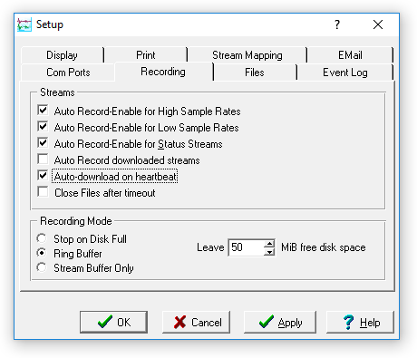
Tick the Auto-download on heartbeat check-box.
Click


Using the FILING transmission mode with Auto-download on heartbeat ensures that Scream! receives all new data whenever it can, regardless of the configuration of any devices between Scream! and the instrument.
10.5.3 DUPLICATE

Selecting this mode instructs the DM24 to transmit streams directly to clients (as for DIRECT mode) but also to store all data into Flash storage (as for FILING mode).
If a client fails to acknowledge a block, the digitiser does not attempt to retransmit it.
Heartbeat messages are not sent in DUPLICATE mode.
10.5.4 DUAL

Selecting this mode instructs the digitiser to transmit any continuous streams directly to clients as for DIRECT mode, but to store triggered data into Flash storage as for FILING mode.
If you choose DUAL mode but do not select any continuous streams for output, the instrument will send heartbeat messages as for FILING mode. Scream! can pick these up and download new data as necessary.
10.5.5 FIFO (First In First Out)

Selecting this mode instructs the digitiser to begin writing blocks to Flash memory as for FILING mode, but also to transmit data to clients. Data are transmitted in strict order, oldest first; the digitiser will only transmit the next block when it receives an explicit acknowledgement of the previous block.
If the communications link is only marginally faster than the data rate, it will take some time to catch up with the real-time data after an outage. If you want data to be transmitted in real-time where possible but are worried about possible breaks in communication, you should use ADAPTIVE mode instead.
FIFO mode will consider a data block successfully transmitted once it has received an acknowledgement from the next device in the chain. If there are several devices between you and the instrument, you will need to set up the transmission mode for each device (if applicable) to ensure that data flow works the way you expect.
Like all the transmission modes, FIFO mode does not delete data once it has been transmitted. You can still request anything in the Flash memory using Scream! or over the command line. The only way data can be deleted is if they are overwritten (in the RECYCLE buffering mode, see below) or if you delete them manually.
10.5.6 ADAPTIVE

Selecting this mode instructs the digitiser to transmit current blocks to clients if possible, but to store all unacknowledged blocks in the Flash memory and re-send them, oldest first, when time allows. ADAPTIVE mode is best suited for “real-time” installations where the link between digitiser and client is intermittent or difficult of access.
If the communications link is only marginally faster than the data rate, it will usually be busy transmitting real-time data. Thus, it may take a while for the instrument to work through the missed blocks. In this case, and if your client supports it, you may prefer to use the Block Recovery Protocol to request missed blocks where possible.
Caution: Some software packages cannot handle blocks being received out of time order. If you are using such a package, ADAPTIVE mode will not work, and may crash the software.
10.5.7 Transmission mode summary
Transmission Mode: | DIRECT | FILING | DUPLICATE | DUAL | FIFO | ADAPTIVE |
Transmit continuous data: | ✔ | ✘ | ✔ | ✔ | ✔ | ✔ |
Store continuous data: | ✘ | ✔ | ✔ | ✘ | ✔ | ?1 |
Transmit trigger data: | ✔ | ✘ | ✔ | ✘ | ✔ | ✔ |
Store trigger data: | ✘ | ✔ | ✔ | ✔ | ✔ | ?1 |
Heartbeat messages: | ✘ | ✔ | ✘ | ?2 | ✘ | ✘ |
Strict time order: | ✔3 | n/a | ✔3 | ✔3 | ✔ | ✘4 |
Retransmit unacknowledged blocks: | ✔5 | n/a | ✘ | ✘ | ✔6 | ✔6 |
Notes:
Acknowledged data are not stored. Unacknowledged data are stored until they are acknowledged.
Heartbeat messages will only be sent if no continuous streams are enabled
The receiver can request a “rewind” if blocks are not received correctly but retransmission resumes in strict time order
Real-time data are prioritised over missed blocks
Up to 256 blocks can be buffered to satisfy rewind requests
The whole of flash memory is used as a retransmission buffer
10.6 Buffer Memory Usage
Güralp CD24 and DM24 digitisers transmit data over serial links using the BRP protocol. CD24 digitisers with network capabilities also use BRP. These digitisers can operate in one of a number of transmission modes, which were described in the previous section. Some transmission modes involve storing data in the digitiser's internal memory. This section describes how to control the behaviour of the system when the memory becomes full.
Note: If the digitiser is connected directly to an EAM, as it is in a DM24SxEAM digitiser or a 30TDE instrument, the transmission mode should be left in the factory default of DIRECT mode and this section does not apply.
10.6.1 RE-USE
Selecting this mode instructs the digitiser to carry on using the current transmission mode when the Flash memory becomes full, overwriting the oldest data held.
For example, in DUAL mode with RE-USE buffering, the latest continuous data will be transmitted to you as normal, and the latest triggered data may be retrieved from the Flash memory using Scream! or the command line. If, however, you do not download data regularly from the Flash memory, you may lose older blocks. This mode thus lets you prioritise the most recent data held by the instrument.
10.6.2 WRITE-ONCE
Selecting this mode instructs the digitiser to stop writing data to the Flash memory when it is full, and to switch to DIRECT mode automatically.
For example, in FIFO mode with WRITE-ONCE buffering, the station will transmit data to you continuously, but also save it in the Flash memory until it is full. Once full, the instrument will switch to DIRECT mode and continue transmitting, though no further data will be saved. This mode thus lets you prioritise the earliest (oldest) data held by the instrument.